AMAZON multi-meters discounts AMAZON oscilloscope discounts
A variable-voltage inverter (VVI) is basically a six-step, single-phase or three-phase inverter. The need to vary the amount of voltage to the load became necessary when these inverter circuits were used in ac variable-frequency motor drives and welding circuits. Originally these circuits provided a limited voltage and limited variable-frequency adjustments because oscillators were used to control the biasing circuits. Also many of the early VVI inverters used thyristor technology, which meant that groups of SCRs were used with chopper circuits to create the six-step waveform. After microprocessors became inexpensive and widely used, they were used to control the biasing circuits for transistor-type inverters to give these six-step inverter circuits the ability to adjust the amount of voltage and the frequency through a much wider range. Motors needed the adjustable frequency to increase or decrease their speeds from their rating that was determined by the number of poles the motor has when it's manufactured. The voltage of the drive needed to be constantly adjusted as the frequency was adjusted so that the motor received a constant ratio of voltage to hertz to keep the torque constant. This became a problem at very low speeds where motors tended to loose torque.
Fig. 1 shows a diagram of the voltage and current waveform for the VVI inverter. From this diagram notice that the voltage is developed in six steps and that the resulting current looks like an ac sine wave. These are the waveforms that one would see if one placed an oscilloscope across any two terminals of this type of inverter.
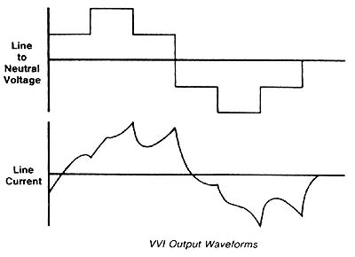
Above: Fig. 1: Voltage and current waveforms for the variable-voltage
input (VVI) inverter.