AMAZON multi-meters discounts AMAZON oscilloscope discounts
Another method of providing variable-voltage and variable-frequency control for inverters is to use pulse-width modulation (PWM) control. This type of control uses transistors that are turned on and off at a variety of frequencies. This provides a unique waveform that makes multiple square wave cycles that are turned on and off at specific times to give the overall appearance of a sine wave. The outline of the waveform actually looks very similar to the six-step inverter signal. An example of this type of waveform is shown in Fig. 1. From this diagram, note that the overall appearance of the waveform is an ac sine wave. Each sine wave is actually made up of multiple square wave pulses that are caused by transistors being turned on and off very rapidly. Since the bias of these transistors can be controlled, the amount of voltage for each square wave pulse can be adjusted so that the entire group of square waves has the overall appearance of the sine wave. Looking at the voltage waveform for the PWM inverter, note that the outline of the ac sine wave still looks like the six-step sine wave originally used in the VVI inverters. The height of the steps of the ac sine wave is also increased when the voltage of the individual pulses are increased. This increases the total voltage of the sine wave that the PWM inverter supplies.
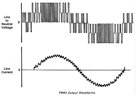
Above: Fig. 1: Voltage and current waveforms for the pulse-width modulation
(PWM) inverter. Notice that the overall appearance of each waveform is
an ac six-step sine wave and that it's actually made of a number of square
wave pulses.
The width (timing) of each square wave pulse can also be adjusted to change the period of the group of pulses that makes up each individual ac sine wave. When the width of the sine wave changes, it also changes the period for the sine wave. This means that the frequency is also changed and is controlled for the PWM inverter by adjusting the timing of each individual pulse. Since adjusting the voltage and frequency is fairly complex, the PWM inverter uses a microprocessor to control the biasing of each transistor. If thyristors are used as in SCRs, the microprocessor will control the phase angle for the firing circuit.
Early PWM circuits used thyristors such as SCRs to produce the square
wave pulses. The control circuit included triangular carrier waves to
keep the circuit synchronized. This sawtooth waveform was sent to the
oscillator circuit that controlled the firing angle for each thyristor.
Today the PWM inverters mainly use transistors because of their ability
to be biased from zero to saturation and back to zero at much higher frequencies.
Modern circuits will more than likely use transistors for these circuits
because they are now manufactured to handle larger currents that are well
in excess of 1500 A.