AMAZON multi-meters discounts AMAZON oscilloscope discounts
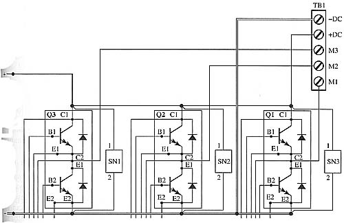
Three-phase inverters are much more efficient for industrial applications where large amounts of voltage and current are required. The basic circuits and theory of operation are similar to the single-phase transistor inverter. Fig. 1 shows the schematic of a three-phase inverter with three pairs of transistors. Each pair of transistors operates like the pairs in the single-phase six-step inverter. This means that the transistor of each pair that is connected to the positive dc bus voltage will conduct to produce the positive half-cycle, and the transistor that is connected to the negative dc bus voltage will conduct to produce the negative half-cycle.
The timing for these transistors is much more critical since they must be biased at just the right time to produce the six steps of each sine wave, and they must be synchronized with the biasing of the pairs for the other two phases so that all three phases will be produced in the correct sequence with the proper number of degrees between each phase.

Above: Fig. 1 Schematic of a three-phase inverter that uses six transistors.