AMAZON multi-meters discounts AMAZON oscilloscope discounts
Fig. 1 (below) shows the electrical diagram of an inverter that uses four transistors instead of four SCRs. Since the transistors can be biased to any voltage between saturation and zero, the waveform of this type of inverter can be more complex to look more like the traditional ac sine wave. The waveform shown in this figure is a six-step ac sine wave. Two of the transistor will be used to produce the top (positive) part of the sine wave, and the remaining two transistors will be used to produce the bottom (negative) part of the sine wave.
When the positive part of the sine wave is being produced, the transistors connected to the positive dc bus voltage are biased in three distinct steps. During the first step, the transistors are biased to approximately half-voltage for one-third of the period of the positive half-cycle. Then these transistors are biased to full voltage for the second third of the period of the positive half-cycle. The transistors are again biased at the half-voltage for the remaining third of the period. This sequence is repeated for the negative half-cycle. This means that the transistors that are connected to the negative dc bus are energized in three steps that are identical to the steps used to make the positive half-cycle.
Since six steps are required to make the positive and negative half-cycles of the ac sine wave, this type of inverter is called a six-step inverter. The ac voltage for this inverter will be available at the terminals marked M1 and M2. Even though the ac sine wave from this inverter is developed from six steps, the motor or other loads see this voltage and react to it as though it was a traditional smooth ac sine wave. The timing for each sine wave is set so that the period of each is 16 milliseconds, which means it will have a frequency of 60 Hz. The frequency can be adjusted by adjusting the period for each group of six steps.
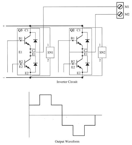
Above: Fig. 1: Electrical schematic of a transistor inverter with the
output waveforms for the ac voltage.

