AMAZON multi-meters discounts AMAZON oscilloscope discounts
Soldering Iron
Soldering is probably the most frequent task you'll perform in repair work. It's also one of the easiest ways to do damage. Competent soldering technique is essential, so let's look at how to do it.

FIG. 7 Proper soldering technique.
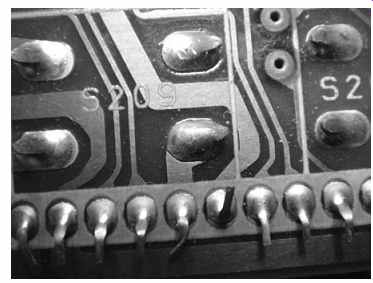
FIG. 8 Good solder joints.
Never solder with power applied to the board! The potential for causing calamity is tremendous. First, you may create a path from the joint, through your iron to ground via the house wiring, resulting in unwanted current. Second, it's very easy for the iron's tip to slip off the joint and touch other items nearby. Make sure power is truly disconnected, remembering that many products don't actually remove all power with the on/off switch. Unplug the item or remove the batteries to be sure.
A good solder joint is a molecular bond, not just a slapping of some molten metal on the surface. The solder actually flows into the metal of the component's leads and the copper circuit board traces. When it doesn't, the result is called a cold solder joint, and it will fail fairly quickly, developing resistance or, in some cases, completely stopping the passage of current.
To get a good joint, first tin the iron's tip. Warm up the iron to its full temperature and then feed a little bit of solder onto the tip. It should melt readily; if not, the tip isn't hot enough. Coat the tip with solder-don't overdo it-and then wipe the tip on the moistened sponge in the iron's base. If you have no sponge, you can use a damp (not dripping wet) paper towel, but strictly avoid wiping the tip on anything plastic.
Melted plastic contaminates the tip badly and is tough to remove.
Once the tip is nice and shiny, put another small drop of solder on it. Press the tip onto the work to be soldered, being sure it makes contact with both the circuit board's pad and the component's lead (or contact point, in the case of surface-mounted, leadless parts). Then feed some solder into the space where the lead and the pad meet, until you have enough melted solder to cover both without creating a big blob. See FIG. 7. To get a good idea of how much solder to use, look at the other pads. See FIG. 8.
As the solder feeds, it should flow into the metal. Check around the edges for smooth integration into the joint. If you see a ring of brown rosin, gently scrape it away with an X-Acto knife or very small screwdriver so you can get a good look. Also check for proper flow around the component lead. Sometimes the flow is fine to the board's pad, but the solder is pooled around the lead without having bonded to it because the iron's tip didn't make good enough contact to get it adequately hot, or the lead had a coating of oxidation that blocked the necessary chemical bonding. In fact, that style of cold solder joint is a major cause of factory defects resulting in warranty claims. At least it was, back when most components had leads. It doesn't occur nearly as often with leadless, surface-mount parts. Frequently, though, the problem is where the solder meets the pad. See FIG. 9.
If the joint looks like a bead sitting on top of the pad, you have not created a molecular bond and will need to reapply the iron. To get enough heat, the wattage of the iron has to be appropriate to the size of the joint. Also, you have to apply some pressure to the tip for effective heat transfer; a very light touch won't do it. Don't press really hard, though, as it won't improve transfer and could cause damage.
If the iron's tip is contaminated, heat transfer will be limited. It should look shiny.
Especially if it has come in contact with plastic, it could have a coating blocking the heat. Although plastic contamination is most easily removed by scraping the tip when the iron is cold, tinning and then wiping a hot tip may cut through the coating.
==
Tip: Before trying to solder tiny, surface-mount parts in a device you're trying to repair, practice on a scrap board. Experience really helps in developing successful soldering technique with these minuscule components.
==
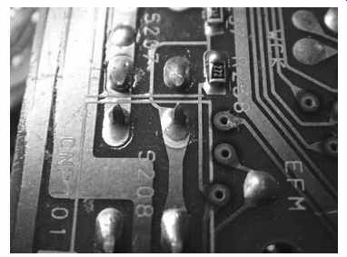
FIG. 9 A cold solder joint. Note how the edge fails to flow into the
surrounding pad.
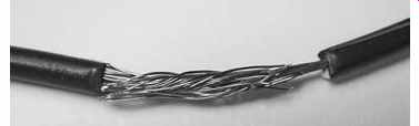
FIG. 10 Stranded wires twisted together
Contamination can occur on the leads of replacement components, too, especially with parts that have sat around for years in your parts drawers. If the leads look dull, apply some fine sandpaper or scrape them clean before attempting to solder them.
They should be shiny for good solder flow.
Once you have a nice, properly flowed joint, remove the supply of solder and then the iron, in that order. If you do have to reflow the joint, add a small amount of new solder so you'll have fresh rosin on the joint to help facilitate bonding.
Soldering leadless, surface-mount components is tricky, mostly because they are so small that it's hard to keep them in place while applying the iron. Make sure the board's pads are completely flat, with no solder blobs on them, and then put the part in place. Hold it down with a small screwdriver placed in the middle of the component while you solder one end. Unless you're anatomically quite unusual, you won't have an extra hand to feed solder to the joint, so put enough solder on the tip to make a crude joint. Don't even worry about molecular bonding. Just tack that side down, even if it's with a bad joint. Then let go of the component and properly solder the other side, taking care to make a good joint. Finally, go back to the first side and do it right. You might have to wick off your first attempt before trying again. Be extra careful not to heat the part too much, or the good side will come unsoldered; those tiny parts conduct heat much faster than do larger components with leads. Also, a lot of heat can delaminate and destroy the component's solderable platings. What works best is adequate heat applied quickly. Get on and off the part with minimum delay.
After soldering, the board will be left with a coating of rosin on and around the new joint. Some techs leave it on, but it's not a good idea because it can absorb moisture over time. Loosen it by gently scraping with the tip of an X-Acto knife or a small screwdriver.
Wipe up what's left with a swab wet with contact cleaner.
To join wires, first twist them together for a solid mechanical connection. If the wires are stranded, try to separate the strands a bit and intertwine them when twisting the wires together. See FIG. 10. If you're using heat-shrink tubing, keep it far from the soldering work or it'll shrink before you get a chance to slip it over the joint. And don't forget to slide the tubing onto one of the wires before entwining and soldering them! It really helps you avoid the expletives from having to cut the wires and start over.
Desoldering Tools
You'll use desoldering tools almost as often as your soldering iron. The two basic types are wick and suckers.
Wick
For small work, wick is the best choice. It's easy to control, doesn't splatter solder all over the area and doesn't run the risk of generating a static charge capable of damaging sensitive components. Its only real drawbacks are that it can't pick up a lot of solder at once, it's a tad expensive and it's not reusable.
To wick the solder off a joint, place the wick on the joint and heat it by pressing the iron to the other side. Applying a little pressure helps. In this case, don't put that extra drop of solder on the tip first or it'll flow right into the wick, wasting some of the braid's capacity to soak up the joint's solder.
When the wick saturates with solder, pull it and the iron away at the same time. If you remove the iron first, the wick will remain soldered to the joint. If desoldering is incomplete, clip off the used wick and try again.
When desoldering components with leads, it can help to form the end of the wick into a little curve and press it against the board so that, when heated, it'll push into the hole in which the lead sits and soak up the solder stuck inside. Be extra careful to keep the wick up to temperature until you pull it away, or you could lift the copper off the board, creating a significant problem.
Sometimes you are left with a film of solder the wick refuses to soak up. If that occurs, try resoldering the joint with a minimum of solder, just enough to wet it down a little. Then wick it all up. The fresh rosin of a new joint can help the wick do its job, carrying the old solder to the wick with it.
Suckers
Solder suckers come in several varieties. The most common are bulbs, bulbs mounted on irons, and spring-loaded.
Bulbs work well when there isn't a lot of solder to remove; they tend to choke on big blobs of it. To use a bulb, squeeze the air out of it, heat up the joint with your iron, position the bulb with its nylon tube directly over the molten solder, get the tube into the solder and relax your grip on the bulb. Although the end of the bulb is plastic, it won't contaminate your iron's tip because the plastic used is a high-temperature variety that doesn't melt at normal soldering temperatures.
After a few uses, the tube may clog with solder. Just push it inside with a screwdriver, being careful not to pierce the bulb. If it's so clogged that you can't budge the solder, pull the tube out and expel the plug from the other end. Eventually, the bulb will fill up and you'll have to remove the tube to empty it anyway.
When you have a large joint with lots of solder, a spring-loaded sucker is the only thing short of a professional vacuum-driven desoldering station that will get most or all of the solder in one pass. Cock the spring and then use it like a bulb.
The fast snap of a spring-loaded sucker can generate a static charge reputed to be capable of damaging sensitive parts, especially MOSFET transistors and integrated circuit chips of the CMOS variety. To be on the safe side, don't use one on those kinds of parts.
Rework Stations
Solder removal gets trickier as parts get smaller. Some of today's surface-mount parts, which have no leads poking through holes in the board, are getting so small that traditional soldering and desoldering tools are inadequate for working on them.
Surface-mounted integrated circuits (IC chips), especially, may have dozens of leads so close together that manual soldering is impossible. To cope with the problem, advanced repair centers use rework stations. These systems have specialized tips made to fit various IC form factors, and they can resolder as well as desolder. Alas, rework stations are quite expensive and out of reach of most home-based repairers.
Power Supply
When powering a device from your bench power supply, you need to consider several factors for successful operation, and to avoid causing damage to the product.
Connection
Many battery-powered items also have AC adapter jacks offering a convenient place to connect your supply. The usual style of connector is the coaxial plug. See FIG. 11. These plugs come in many sizes, and both inside and outside diameters vary. If you can find one in your parts bins that fits, perhaps from an old AC adapter or car adapter cord, you're in luck! Sometimes you can use a plug with a slightly different diameter, but don't force things if it isn't a good fit. You may find one that seems to fit but doesn't work because the inner diameter is too large, so the jack's center pin won't contact the inner ring of the plug.
The polarity of the plug is paramount! Don't get this backward or you will almost certainly do severe damage to the product as soon as you hit the supply's power switch. Coaxial plug polarity is usually printed on the device somewhere near the jack, and it will be on the AC adapter as well. Most modern products put positive on the tip and negative on the outer sleeve, but not all. Always check for the polarity diagram. It should look like one of these:
- + - + -
If there's no adapter jack, or you choose not to use it, you can connect clip leads to the battery terminals of most devices. This should work fine with anything using standard, off-the-shelf cells like AAs. The convention is to use a red lead for positive and a black one for negative, and I strongly suggest you do so to avoid any possible polarity confusion, which could be disastrous.
In a typical case, you open the battery compartment and find a bunch of springs and contacts, one set for each cell. Most of them link one cell's positive terminal to the next one's negative, forming a series string. One spring (the negative terminal) and one positive terminal (usually a flat plate or wire) feed the circuitry from each end of the string. Which are the two you need?
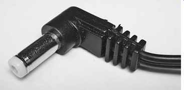
FIG. 11 Coaxial power plug
Sometimes the positions of the terminals offer mechanical clues. If you see two connected directly to the board, or if they're placed such that they could be, those are probably the right ones. Also, if one set of terminals is on a flip-out or removable door, that pair is not what you're looking for. If you find no such hints, use your DMM's continuity feature to determine which terminals are connected to adjacent ones.
Whatever's left should be the two magic terminals.
If you can reach the terminals with probes while the batteries are installed, pull the cells out, use your DMM to measure each one and then reinstall them. Add up the voltages to get the total series voltage, and then look for it between terminals.
Make sure the product is turned off, so it won't pull the voltage down. Only the two correct terminals will show your calculated voltage; any other combination will be significantly lower.
If the device uses a square 9-volt battery, the larger, petal-like terminal of the unit's snap-on connector is positive. Nine-volt gadgets are pretty rare these days, but you will encounter this battery style if you work on old transistor radios or tape recorders. Some digital answering machines and clock radios still use 9-volt batteries for memory backup.
In products with proprietary lithium-ion batteries, it's often possible to provide power through the device's terminals, but not always. Some of them, especially camcorders and laptops, use "smart" batteries containing their own microprocessors, and the device won't recognize power applied to the terminals without the data those micros provide.
Many smaller items, like digital cameras, may have three terminals. Two are for power, of course, and the third one is for a temperature sensor to prevent overheating during the charge cycle. Usually, these devices can be powered from a power supply, with the third terminal left unconnected.
To determine which terminal does what, look at the battery. You probably won't find any polarity markings on the product, but they are nearly always printed on the battery, and you can place it in the orientation required for insertion and see which terminals line up with the ones in the unit. You want the + and - terminals, of course. The other one may be marked "C" or have no marking at all.
If the battery is also unmarked, try measuring its voltage with your DMM. Most commonly, the voltage output is from the two outer terminals, with the sensor terminal between them. Once you find the right terminals, you'll also know the polarity. This assumes, of course, that the battery has at least a little charge on it; there's no way to read a dead battery, and don't even think of trying to apply a charge from your power supply without knowing the polarity. Lithium-ion batteries are nasty when they burst. You can get hurt. Even when you do know the polarity, putting too much current through lithiums too fast can make them go boom.
Voltage
Set the supply's voltage before connecting it to the device, and try to get it pretty close to what the unit expects. Most products list their battery voltages either on the back of the unit or on the battery, in the case of proprietary cells. In AA- or AAA-driven units, just multiply the number of cells by 1.5. Remember, though, that NiMH (nickel-metal hydride) rechargeable cells are only 1.2 volts each. If you run into the rare item that is made for use only with rechargeables, multiply by 1.2 instead. Some digital cameras and MP3 players fall into that category; they won’t function with alkalines or other throw-away cells, and the higher voltage may damage them.
Most hobby-grade power supplies have analog meters, and they can be off by quite a bit. To keep things more accurate, use your DMM to set the voltage. Don't worry about millivolts; just stay within half a volt or so and you should be fine. Even lithium-ion batteries start out a little above their rated voltage when fully charged, with the voltage dropping as the charge is drained. The curve is a lot flatter than with other battery technologies, though, which is why it's a good idea to match the rated voltage the best you can.
Once you've set the voltage, turn the supply back off and connect the leads, double-checking the polarity. Then, hit the switch and pray. No smoke? Great! You're in business.
Current
The current drawn by a device will vary, depending on what the unit is doing.
Especially with any product employing moving parts like a hard drive platter or laser optical head, current demand goes way up during mechanical motion, dropping again when movement ceases.
As long as your supply has sufficient current capacity, it doesn't matter. If, however, the supply has enough for some modes of a device's operation but not others, the results can be unpredictable.
This issue crops up during service of camcorders and hard drive-based MP3 players. The drive spins up or the tape loads, and suddenly the device shuts down or its micro gets scrambled due to the lowered voltage from an overloaded supply. If your supply has a current meter, keep an eye on it to be sure you're never pulling the supply's maximum current. If the meter does show maximum, the product's demand is probably exceeding what the supply can offer, and the voltage is dropping.
Transistor Tester
Using a transistor tester requires taking the transistor out of the circuit. Doing so ranges from easy, with small-signal transistors, to a hassle, with power transistors mounted on heatsinks. Transistors have three leads (see Section 7), so you'll have to disconnect at least two of them, though it's usually easier just to desolder all three and pull the part off the board. Big power transistors with metal cases employ the case as one terminal, usually the collector. With those, you may find it more convenient to leave the part on the board and disconnect the other two terminals, especially if they're connected with wires, rather than directly to circuit board traces.
There are several basic types of transistors, and testing procedures vary. With some transistor testers, you need to know which terminal is which, while others will try out all the combinations automatically and recognize when the correct configuration has been found.
Fancy transistor checkers can evaluate a transistor's characteristics in actual operation by using the transistor as part of an oscillator built into the checker. They can show you the part's gain and leakage. For most service work, such sophisticated measurement is unnecessary. Usually, you just want to know if the part is open or shorted. A transistor can be "leaky," passing reverse current or allowing flow between terminals when it shouldn't occur, but it doesn't happen often.
To test a transistor, connect its three leads as specified in your tester's instructions, and read whatever info it gives you. There are too many types of testers to detail their operation here.
Some DMMs include transistor test functions. If yours has a little round socket marked E, B and C, you have a transistor tester! Capacitance Meter
Checking capacitors requires disconnecting at least one of their leads, because other circuit elements will distort the reading. Be absolutely sure to discharge the capacitor before testing it, especially with electrolytic caps, which can store a lot of energy capable of trashing your tester.
Turn the meter on and connect the capacitor to the input terminals. Some meters have special terminals into which you can press the cap's leads. You can use those or the normal clip leads, whichever is more convenient. If the capacitor is polarized, connect it the right way around, + to + and - to -! See Section 7 for polarity marking styles.
If your meter is autoranging, it'll step through its ranges and read the cap's value. If it isn't, begin at the most sensitive range, the one that reads pf (picofarads, or trillionths of a farad) and work your way up until the "out of range" indicator goes away and you get a valid reading. When you're finished, unhook the capacitor and discharge it. Very little energy is put into the component to test it, so you can short across its terminals without worry.
The meter will show you the value of the capacitor in fractions of a farad. Some types of capacitors, especially electrolytics, have fairly wide tolerances, or acceptable deviations from their printed values. Typically, an electrolytic can be off by 20 percent of its stated value even when new. Manufacturers deliberately err on the high side to ensure that filtering will be adequate when the caps are used in voltage smoothing applications, as many are. If the cap reads a little high, don't worry about it. If it reads a little low, that may be okay too. If it reads more than 20 percent low, suspect a bad cap.
And if you can't get rid of the out-of-range indicator on any scale, the cap is probably shorted or very leaky. Open caps will read as extremely low capacitance.
Only very specialized capacitance meters can read an electrolytic cap's equivalent series resistance (ESR). This parameter goes up as a cap ages, eventually interfering with proper operation and rendering the cap useless. A cap can still be bad even though it looks fine on a normal cap meter. But if it reads significantly below its intended value, or shows a short or an open, it’s bad.
Signal Generator
A signal generator is used to replace a suspected bad or missing signal temporarily so notice what its insertion will do to a circuit's behavior. Inserting a signal is a very handy technique when working on audio circuitry. It can also help you check clock oscillator function in digital gear or sub for a missing oscillator in radio equipment.
For audio testing, it's best to use a sine wave somewhere in the lower middle of the audio spectrum, at around, say, 1 kHz. Using a sine wave prevents the generation of harmonics that could damage the amplifier under test, the speakers or your ears.
For clock oscillator substitution, set the generator to the same frequency as the missing oscillator (it should be marked on its crystal), and use a square wave. Set the peak-to-peak voltage of the generator just below whatever voltage runs the chip normally doing the oscillating. Don't exceed it, or you could "latch" and damage the chip.
For radio oscillator substitution, use a sine wave at the frequency of the missing oscillator. It's probably best to feed the signal from the generator through a capacitor of around 0.01 µf to avoid loading down the radio's circuits. Set the peak-to-peak oscillator voltage to something less than the power supply feeding the radio's stage.
Usually some fraction of a volt is plenty in this kind of experiment.
Frequency Counter
Frequency counters are used to adjust a device's oscillators to a precise, accurate frequency, or to verify a frequency. Radio and TV receivers, video recorders and even some all-digital devices can require carefully set oscillators for proper operation.
Frequency measurement also may aid in troubleshooting optical disc players.
A counter works by totaling up how many cycles of an incoming waveform go by in a period of time specified by the instrument's gate period. The gate opens, the waves go by, it counts 'em and puts the count on the display. That's it.
Ah, if only real life were that simple! Sometimes this works and gives you a correct count; sometimes it doesn't. For one thing, how does the counter know when a cycle has occurred? Unlike the trigger on a scope, the counter's trigger is very simple: it looks for zero crossings, or places where the signal goes from positive to negative, and counts every two of them as one cycle. For simple waveforms with little or no noise, that works great.
A lot of signals have noise or distortion on them, however, that can confuse the zero-crossing detector, resulting in too few or too many counts. If you connect a counter to a test point using a scope probe and then switch between 10X and 1X on the probe, the count will probably change a little bit, with a lower count in the 10X position. Which one is the truth? It's hard to say for sure. Usually, the count is more accurate when the input voltage is lower because noise on the signal is less likely to trip the zero-crossing detector. If it gets too low, though, the detector may miss some cycles altogether, resulting in an incorrect, low count. If you get counts that seem very low for what you were expecting-say, a 10-MHz oscillator reads 7.2 MHz-the input voltage is likely too low and the detector is missing some cycles. If the count seems too high, the signal may be noisy and also could be too strong, adding false cycles to the count.
Complex, irregular signals like analog audio, video and digital pulse trains cannot be counted in any useful way with a frequency counter. What comes in during each gate period will vary, so the display won't settle down. Also, correct tripping of the zero-crossing detector is impossible. Use this instrument only for simple, repeating waveforms such as those produced by oscillators.
Back in Section 2, we looked at precision and accuracy, and how they affected each other. Nowhere does this issue come up more often than with frequency counters.
Most counters have lots of digits, implying high precision. Accuracy is another matter.
The count you get depends on how long the gate stays open. That is controlled by a frequency reference, which is an internal oscillator controlled by a quartz crystal.
In a very real sense, the counter is comparing the incoming signal's frequency to that of the instrument's crystal, so variation in the crystal oscillator's frequency will skew the count. Crystals are used in many oscillator applications requiring low drift, but they do wander a bit with temperature and age. Most counters have internal trimmer capacitors to fine-tune the crystal's frequency, but setting them requires either another, trusted counter for comparison; an oscillator whose frequency is trusted; or some cleverness with a shortwave radio that can receive WWV, the National Bureau of Standards atomic clock's time signal originating from Fort Collins, Colorado. That station broadcasts its carrier at a highly precise, accurate frequency, and it’s possible to compare it audibly to your counter's oscillator, using the radio as a detector. When they zero-beat, or mix without generating a difference tone, your counter is spot on frequency. Performed very carefully with a counter that's been fully warmed up, zero beating against WWV can get you within 1 Hz, which is darned good.
On many counters, the gate time can be selected with a switch. Longer gate times give you more digits to the right of the decimal point, but their accuracy is only as good as the counter's reference oscillator. Don't take them terribly seriously unless you are certain the reference is correct enough to justify them. If your right-most digit specifies 1 Hz but the reference is 20 Hz off, what does that digit mean? For audio frequencies, you'll need a fairly long gate time to get enough cycles to count. For radio frequencies, a faster gate time is more appropriate.
Connecting a counter to the circuit under test can be tricky in some cases. Loading of the circuit's source of signal generation is a real problem, pulling it off-frequency and affecting the count significantly. Especially when you touch your probe directly to one lead of a crystal in a crystal oscillator, the capacitance of the probe and counter can shift the oscillator's frequency by a surprising amount. To probe such a beast, look for a buffer between the oscillator and everything else, and take your measurement from its output. Since the circuit itself also may load the oscillator, it's highly likely that a buffer is there someplace. These days, most crystal oscillators are formed with IC chips, rather than transistors, with the buffer being on the chip and the frequency output coming from a pin not connected to the crystal. Use your scope to find it and then connect the counter to that pin.
Analog Meter
Using an analog VOM or FET-VOM requires interpreting the position of a meter needle, rather than just reading some numbers off a display. Why would you bother with this? That meter needle can tell you some things a numerical display can't. Specifically, how it moves may give you insight into a component's or circuit's condition.
Taking most kinds of measurements with a VOM is pretty much like taking them with a DMM. VOMs are not autoranging, so you have to match the selector knob's scale to the markings on the meter movement. Also, you need to zero the ohms scale with the front-panel trimmer knob every time you change resistance ranges. Select the desired range, touch the leads together and turn the trimmer until the meter reads 0 ohms.
Unlike FET-VOMs and VTVMs, VOMs have no amplification, so they load the circuit under test much more when reading voltage than do other instruments.
This is of no consequence when measuring the output of a power supply, but it can significantly interfere with some small-signal circuits.
VOMs can pull a few tricks not possible with their digital replacements. Slowly changing voltages will sway the meter needle in a visually obvious way, instead of just flashing some numbers. A little noise won't affect the reading, either, thanks to the needle's inertia. A lot of hum on a DC signal can vibrate the needle in a very identifiable manner. Some old techs could read a meter needle almost as if it were a scope! If you don't have a capacitance meter, you can gauge the condition of electrolytic capacitors with the meter's ohms scale. This works pretty well for caps of about 10 µf or more; it doesn't work at all for anything under 1 µf or so. Set the meter to its highest range and touch the test leads together. When the needle swings over, use the trimmer on the front panel to adjust it to read 0 ohms. (If the needle won't go that far, the meter needs a new battery!)
Connect the leads to the discharged cap, + to + and - to -, and watch what happens. The meter should swing way over toward 0 ohms and then gradually fall back toward infinity. The greater the capacitance, the harder the needle will swing, and the longer it'll take before it finally comes to rest. If the needle doesn't fall all the way back, the cap is leaky. If it doesn't swing toward zero, it's open or of low capacitance.
The meter applies voltage from its battery to the capacitor, so be sure the cap's voltage rating is higher than the battery voltage or you could damage the cap. Some meters use 9-volt batteries for their higher resistance ranges. If yours does, it's wise not to try this test on caps rated lower than that. If your meter uses only an AA cell, there's nothing to worry about.
The ohms scale can also be used to check diodes and some transistors, just as with a DMM.
Contact Cleaner Spray
Cleaner spray is handy stuff, especially for use with older, analog equipment. Volume controls, switches and sockets can all benefit from having dirt and oxidation cleaned away. When controls exhibit that characteristic scratchy sound, it's time to get out the spray.
For spray to be effective, you have to be able to get it onto the active surface of the control or switch. Sometimes that's not easy! If you look at the back of a potentiometer, or variable resistor, you may find a notch or slot giving you access to the inside, where the spray needs to be. Always use the plastic tube included with the spray can! Trying to spray the stuff in with the bare nozzle will result in a gooey mess all over the inside of your gear. Once you get some spray into the control, rotate it back and forth a dozen times. That'll usually cure the scratchies.
Switches can be a bit tougher. Some simply have no access holes anywhere. If you can't find one, you'll have to spray from the front, into the switch's hole. Never do this where the spray may come into contact with plastic; most sprays will permanently mar plastic surfaces.
Trimmer capacitors should not be sprayed. They have plastic parts easily damaged by the spray and may lose function after contact with it.
Do your best not to splatter spray onto other components. Wipe it off if you do.
Also, it could shatter a hot lamp, so don't use it near projector bulbs. And, of course, avoid breathing it in or getting it in your eyes. Spray has a nasty habit of reflecting back out of the part you're blasting, right into your face. Keep your kisser at least 12 inches away. Farther is better.
To avoid making a mess or getting soaked, try controlling the spray by pressing gently on the nozzle until only a gentle mist emerges. Some cans have adjustable spray rates, but many don't. Some brands are more controllable than others, too.
Experiment with this before you attack expensive gear.
Component Cooler Spray
Cooler spray can be incredibly useful for finding thermal intermittents. If a gadget works until it warms up, or it works only after it warms up, normal troubleshooting methods can be hard to implement, especially in the second case. How are you going to scope for trouble in something that's working?
Before hitting parts willy-nilly with cooler, decide what might be causing the trouble. The most likely candidates for cooler are power supply components like transistors and voltage regulators, output transistors and other parts with significant temperature rises during normal operation.
As with cleaner, use the spray tube, and try controlling the spray rate. Also, the same caveats regarding breathing it in and getting hit in the face hold here. This stuff is seriously cold and can damage skin and eyes. A small amount hitting your hands won't do you any harm, but I shudder to think of a single drop's splattering on your cornea.
If spraying a suspected component reverses the operational state of your device (it starts or stops working), you've most likely found the trouble.
After spraying, moisture will condense on the cold component. Be sure to kill the power and wipe it off.