AMAZON multi-meters discounts AMAZON oscilloscope discounts
[part 1 | part 2 | part 3 | part 4]
Although the principles we've covered apply to pretty much all electronic devices, various product categories are different enough that they benefit from specific troubleshooting techniques. Let's look at some of the most common gadgets, their typical problems, and how to approach their repair.
Switching Power Supplies
Since you'll run into issues with switching power supplies in many kinds of machines, let's cover them first, before looking at the products in which they take up residence.
How They Work
Switching supplies rectify the incoming AC into DC and then chop it at high frequency, pulling current through a transformer's primary coil with each pulse. Using a high frequency allows the energy to be replenished on the other side of the transformer much more frequently than with the old linear approach, which was limited to the 60-Hz line frequency. So, the transformer doesn't have to convert as much power at one time and can be a lot smaller. The approach also keeps the chopper transistor either saturated (turned all the way on) or cut off (turned all the way off) most of the time, resulting in high efficiency, since it spends almost no time per pulse in its midrange (partially turned on), where transistors act like variable resistors, with all the attendant heat resistance generates.
What Can Go Wrong
Controlling those high-frequency pulses, with their fast rise and fall times, is tougher and stresses the components a lot more than did low-speed linear circuits. The fast pulses with high-voltage peaks punch holes in transistors' substrates, and the rapid charging and discharging of filter capacitors wears those out too. Consequently, switchers fail significantly more often than do linear supplies. Nonetheless, very few products still use the old technology; switchers are everywhere, from computer supplies to little AC adapters and chargers for cameras and cell phones.
Is It Worth It?
Unless the transformer is shorted or open, it's generally worth repairing a switcher, especially if it's in a product you want to get working again. It might be a waste of effort on an AC adapter that could be easily replaced. The transformer rarely goes bad, though I've seen it happen now and then with that ubiquitous cousin of the switching supply, the backlight inverter. The high voltage of an inverter's output sometimes breaks down the insulation between the transformer's windings. In a normal, AC powered switcher used to create low-voltage DC output, that's an unlikely scenario.
If multiple semiconductors have blown from a chain reaction feeding voltage from one stage to the next, fixing the supply may be more trouble than it's worth.
Especially if the pulse-width modulator chip is dead, getting the part can be a hassle.
The Dangers Within
To service a switcher, disconnect the power first! Never work on one with power applied unless you have an isolation transformer. Even then, don't work on powered switchers until you gain a fair amount of experience. The dangers are real and significant. Did you take off your wristwatch and all jewelry? It's especially important now. Be sure to wear shoes, too.
Switchers are organized in two sides: the primary side, connected to the AC line and with no ground connection to the rest of the product's circuitry, and the secondary side, isolated from the AC line by the transformer and connected to circuit ground in the rest of the device. Linear supplies share the same basic organization, except that there's no circuitry on the primary side beyond a fuse.
The primary side of a switcher is where most of the trouble is, and also most of the danger. The chopper circuit stresses its transistor harder than any other component in the supply, leading to frequent failures. The side's direct connection to the house wiring makes service hazardous because any contact between you and ground completes the circuit. The secondary side is at lower voltages, and its isolation from the line means it's a lot safer. Some switchers go as far as having holes in the circuit board between sides for some extra protection from arcing over and loss of isolation.
How to Fix One
Most switchers fail from bad electrolytic capacitors, blown rectifiers or a dead chopper transistor. Look at the capacitors first. Any bulges? Change them. Leakage? Change them. Anything at all unusual about their appearance? Change them! Checking the rectifiers is easy enough if they're separate diodes. When you have a bridge rectifier, with all four diodes in one package, each diode must be tested as if it were a separate part. Take a look at the bridge rectifier diagram back in Section 7. With all power disconnected and the big electrolytic near the bridge discharged, desolder the bridge from the board and use your DMM's diode function to test each diode in it. You should see around 0.7 volts drop at each diode in the forward direction and an open circuit in the reverse direction, as with any silicon diode. If you find an open or a short in any of the diodes, replace the bridge.
The chopper is the big transistor, probably heatsinked, on the primary side of the transformer. Some choppers are bipolar transistors, but most are power MOSFETs.
If the fuse is blown, it's a good bet the chopper has shorted out. The transistor can fail open, too, in which case the fuse might still be good. The transistor may have shorted and then opened, and the fuse may or may not have survived the momentary overcurrent. It's an old technician's anecdote that transistors are there to protect fuses! Check the chopper using the out-of-circuit techniques discussed in Section 7.
If you have an isolation transformer, you can do some powered tests before pulling parts. Check the voltage across the big cap on the primary side of the supply, near the chopper. Remember that you can't use circuit ground on this side. The negative terminal of the cap will be your reference point, where you'll connect the meter's black lead. You should see at least 300 volts. If it's much less, suspect a bad bridge rectifier. If it's zero, the fuse is probably blown, which could mean a bad bridge, a shorted cap or a bad chopper.
It's best not to try to scope the chopper directly, as the voltages are very high.
The safer approach is to scope the secondary side of the transformer, using normal circuit ground. Many switchers have multiple taps on the secondary winding. Any of them will do, as long as it's not the one connected to circuit ground. If the chopper is running, you'll see pulses at a significantly lower voltage than what's on the other side. They won't be tiny, though. Expect anything from 10 to perhaps 60 volts from the baseline to the peak. No pulses? She ain't running.
If the chopper is good but isn't running, suspect the pulse-width modulator (PWM) chip or the regulation circuitry near the output. Open zener diodes on the secondary side can allow the output voltage to rise too high, activating protection circuitry and shutting down the PWM, or even tripping the crowbar, deliberately blowing the fuse. No pulses, no chopper, no operation.
If the supply is running but not putting out proper power, caps on the secondary side are the primary suspects. Scope them. If you see much of anything but DC on an electrolytic that has one lead going to ground, change it. Either its capacitance has declined, its ESR has risen, or both. If you change the cap but the waveform still looks noisy, look for a leaky diode feeding the cap.
Finally, remember that most switchers will shut down if output current demand exceeds their safe limits. Some may blow their fuses for the same reason. A short somewhere else in the machine may be pulling too much current and causing the supply to act like it's broken.
Audio Amplifiers and Receivers
Audio amps and receivers are at the centers of all home theater setups. The units have to produce significant power to drive speakers, so they include a fair amount of heat-generating circuitry prone to failure.
How They Work
Though today's audio amplifiers and receivers employ digital signal processing for surround sound decoding, delay effects and sophisticated tone controls, power amplification is still an analog process in nearly all of them. The exception is the Class D digital amplifier, which converts the incoming signals to pulse-width modulation of a high-frequency carrier. The pulses are then current-amplified, with a lot of amperes available in each pulse. At the output, a smoothing filter blends them back into audio before sending them to the speaker. Class D amplifiers are used mostly in automotive applications because they are extremely efficient and can develop a lot of power in a small box without getting very hot. Fidelity can be quite high in Class D, but achieving it isn't easy. So, home audio gear, which lives in a quiet environment more conducive to critical listening, has stuck with analog amplification, a very mature, refined technology capable of exceptionally good sound reproduction.
Before home theater, the chain was simple: preamp, through tone controls, to drivers and outputs. Not anymore! Input may come from analog jacks, digital coaxial or digital optical cables, with varying sample rates and bit depths (number of bits per sample). Several formats of multichannel encoding are used, too, and the unit has to be able to handle them all. Once the desired signal processing has been accomplished, the data is converted back to analog and applied to conventional audio circuits.
Capacitive coupling, with each stage connected to the previous and next stages via capacitors, is rarely used because the caps cause phase shift and rolling off at the low end of the audio frequency spectrum. Most of today's amplifiers are directly or resistively coupled, for maximum fidelity.
Because DVDs brought audio with more than two channels to the home, the conventional stereo receiver is all but gone; newer units have at least five channels: two front, two rear and one subwoofer for deep bass. Some have seven. What's the difference between and woofer and a subwoofer? One of them can operate under water! No, seriously, a subwoofer is for reproduction of only the lowest frequencies, usually under 100 Hz, while a woofer's range may extend into the hundreds of hertz. With today's small "satellite" speakers unable to reproduce low frequencies much at all, the subwoofer is really a woofer, but the term has stuck. One defining characteristic is that there's only one of them, as opposed to the usual separate woofer for each channel, because very low audio frequencies have little directionality, filling the room regardless of the speaker's position. Thus, there's no separation, stereo or otherwise, and the sense of spatiality comes from the higher frequencies being reproduced by the satellites.
For every channel there is a complete amplifier chain culminating in an output stage. Many receivers use power amplifier modules for their outputs, but higher-end units still go with discrete stages because they're reputed to sound better.
What Can Go Wrong
The power supply works mighty hard, at least when the volume is turned up high.
Moving a lot of air with the subwoofer, necessary for the serious bass frequencies found in movie explosions and such, takes an especially large amount of power. While modest home systems may have a hundred watts available for that, self-amplified subwoofers with several thousand watts have been marketed. Of course, people utilizing the full power of those things can't actually hear their movies anymore, but that's what subtitles are for, right? Plenty of receivers still use linear power supplies because switchers can introduce high-frequency noise that's hard to eliminate. To power five channels of 100 watts each takes some serious iron in the transformer, along with high-current diodes, hot-running linear voltage regulators and huge electrolytic capacitors. There's a reason receivers weigh so much! All that heat and high current take their toll, especially on the diodes and capacitors. Even with the generally higher reliability of the linear approach, power supply failures in receivers are common.
The most trouble-prone parts of a receiver are the output stages. Whether modules or separate transistors, they are where the current is. Plus, they operate in their linear regions, neither saturated nor cut off at any time (one hopes!), so they're essentially resistors, dissipating power supply current as heat. Look for large heatsinks and you'll find the output stages.
With all those jacks, input switches and interconnections between boards, signals can be impeded by bad connections, causing them to crackle or drop out completely.
Phono preamp sections are especially vulnerable to this, as they handle the very tiny signals generated by magnetic phono cartridges, and it doesn't take much to stop those. Cartridges put out around 5 mv peak-to-peak, compared to the 1-volt standard for line-level audio. Still, even with the higher-level signals, ratty connections in the signal path cause many receiver problems.
Speaker protection circuits sense when there is significant DC offset, or variance at the midline of the signal waveform from 0 volts. When offset occurs, there's a fault somewhere in the amplifier, and the protection circuits disconnect the speakers to prevent excessive power supply current from burning out their voice coils. At least that's how they're supposed to work. Now and then the protection circuit malfunctions, going into protection mode when nothing is really wrong.
Is It Worth It?
Not much in a receiver's power supply or amplifier chain is especially expensive or hard to get, so most receivers of any real value are worth repairing. Output modules are available from online parts houses, as are power transistors. You aren't going to find the DSP (digital signal processing) chips, but it's highly unlikely you'll need them anyway. In receivers, the power-handling areas are usually where the mischief lurks.
Dangers!
Most output stages are complementary push-pull types fed by positive and negative power supply lines. (A push-pull design with only one power supply polarity is called quasi-complementary.) The supply lines may have 30 to 80 volts or so on them, so they are capable of shocking you. And should you be unlucky enough to touch both at the same time, you could come in contact with 160 volts or more.
Receivers with fluorescent display panels have small inverters supplying the panels with the few hundred volts required to light them up. The inverters are typically located on boards just behind the displays.
Heatsinks can get mighty hot, so avoid touching them if the unit has been on for awhile, especially at high volume.
How to Fix One
Servicing a receiver is very much a process of elimination. The first thing to consider is whether the problem affects all the channels. If so, head for the power supply. One channel could have a short pulling everything down, but the supply is the first thing to check. If only one channel is affected, that's where you'll find the trouble; the supply has to be okay, since it's powering the other channels properly.
Power Supply Problems
With a linear supply, testing is pretty painless, compared to the ordeals of working on a switcher. The transformer comes early in the chain, and what's between it and the AC line is easy to evaluate without power applied. If the unit is dead, check the fuse.
As with other products we've examined, a blown fuse almost always means something pulled too much current through it. Look for shorted rectifiers or a short somewhere farther down the line, on the other side of the transformer. If there's a connector you can pull to isolate the supply from the rest of the unit, try doing that to see if the overcurrent situation persists.
Output Stage Problems
A shorted output stage will pull the supply's output down toward ground, possibly blowing the fuse. Sometimes there's enough resistance between the shorted transistor or module and the supply to limit the current to a value below the fuse's rating, so it survives. The telltale sign of a shorted output stage is a loud hum through a speaker connected to that stage. However, other channels' outputs may also produce the hum because they're fed from the same supply line that's being pulled down by the bad one. They won't hum as loudly, though. Scope the output. If you see DC with something resembling a 60-Hz sawtooth wave riding on it, you've got a short.
Frequently, changing the output transistors or the module takes care of everything. Sometimes, and particularly with discrete designs (no module), the driver transistors may be shorted too. Also, always check the resistors in series with the emitters of the power transistors in discrete stages. The overcurrent can really cook those babies, altering their values or even cracking them. Most techs replace the emitter resistors as a matter of course when they change output transistors.
In direct-coupled designs, shorts in one stage may blow surrounding stages. I've seen a shorted output transistor take out every transistor in its channel, right back to the input jacks! That used to happen frequently in early designs, but it's still possible even now. Ironically, the costliest units are more likely to have extensive damage, thanks to their closely coupled stages with few or no components to isolate them.
That kind of circuit sounds the best when it works, but it's a mess when it breaks.
At the inputs to the driver stage, look for diodes or zeners. They're used to set the bias points, keeping the positive and negative halves of the output stage just slightly turned on even when there's no signal or it's very small. An open zener or a shorted diode can make the bias go wild, causing the outputs to conduct themselves to death.
Changing the transistors without checking the bias just means you'll need more transistors in a few minutes.
The damage can proceed the other way, too, from input to output. Again, designs with close coupling are the most susceptible because their output stages' bias is set right at the start. If the input transistor shorts, it can drive DC right to the outputs, upsetting their bias and sending them to semiconductor heaven. Or, considering the heat, perhaps it's the other place.
Although it seems like diagnosing an amplifier should be very straightforward, the interdependence of DC levels from stage to stage can turn a romp into a nightmare. If you find yourself going around in circles, disconnect the output stages from the power supply and scope their input lines. You should see normal audio with some DC offset.
Most receivers use bipolar output transistors, so the bias is a matter of base current, not voltage. With no power to the transistors, the offset may be significant, but it shouldn't be close to the power supply rails.
Small-Signal Problems
Small-signal issues are like those in any other device. You could have a bad cap, a bad transistor, and so on. To determine whether the problem is in the small-signal sections, test the various inputs. If any of them works properly, the power supply and output stages are doing their jobs. The various signals-digital, analog, radio-wind up as analog audio at the inputs to the power amplifier stages, starting with the line-level (1 volt peak-to-peak) stage. If no input works, go back to the beginning of the signal path, using the simplest one possible: an auxiliary analog jack. Feed it a signal from an audio player, select it on the front panel as the active audio source, and scope your way through the low-level stages to see where it stops. Oh, and be sure to turn the "tape monitor" switches off! They interrupt the audio path so a tape deck can be inserted in line with it. With no deck connected, the audio comes to a dead end, never reaching the power amplifiers.
With their multiple input paths, receivers have more connections through switches than most devices, offering plenty of opportunities for bad connections.
Newer units often have electronic switching, rather than the old rotary or pushbutton switches used for decades. Noncontact switching is more reliable, but a blown analog switch chip will stop things dead. It's pretty rare for just one of the chip's inputs to fail, though; a bad chip usually kills them all.
Hum isn't always a power supply or output stage problem. If the sound of the hum is thin, with high-frequency content that's a little bit buzzy, and it isn't loud enough to wipe out the audio, there may be a bad ground connection somewhere in the low-level circuitry. As in many products, grounding from the board to the chassis can be mechanical, provided by the pressure between the board's ground lands and the metal tabs into which the board is screwed. Over time, oxidation increases the resistance of those connections, and hum can result.
If the level of the hum varies with the volume control, the source has to be early in the chain, before the control. Try unplugging the audio source from the input jacks.
If the hum disappears, you have a bad cable feeding the jacks or a ground loop between the audio source and the receiver. If it's still there, pull the board and clean the ground lands and the chassis mounting tabs until they're nice and shiny. If that doesn't solve it, check for bad solder joints that may be causing poor grounding.
Disc Players and Recorders
Though inexpensive, CD and DVD players are not simple. They are actually little computers, combined with the mechanical and optical sections necessary to retrieve data from the disc.
How They Work
To find, follow and decode the disc's microscopic optical tracks requires a focused laser beam, a three-axis servo system and a fair amount of computing power. An awful lot has to go right for the data to be read from the disc and transformed into your favorite movie or music.
First, the disc must be accepted into the player, properly seated on the spindle and clamped down. The machine moves the optical head to the center of the disc, where playback will begin. Then the laser turns on and the lens moves up and down while the phototransistors in the head look for a reflected beam from the disc.
If no reflection is detected, the player stops and displays "no disc." Once it sees a reflection, the machine stops the lens when proper focus is found. This is determined by reception of maximum beam strength in the head's center detector with minimum beam strength in the side sensors, indicating optimum spot size. Only if focus is achieved will the player spin the disc and try to read the track. If the lead-in track is found, the sled motor starts moving the head away from the disc's center, and playback begins. As the disc spins, its normal wobbles and eccentricities far exceed the size of its tracks, so the tracking and focus servos keep the lens dancing around in three-dimensional step with their movements. The disc's speed gradually decreases as the head proceeds toward the outer rim, because the linear distance for each rotation increases. The object of the technique, called constant linear velocity, is to keep the speed of the track constant as it goes past the head, so the bits can be crammed in as tightly as possible for maximum disc storage capacity. The spindle speed is controlled by the microprocessor's monitoring the rate at which data is being read from the disc. Only when all these systems work in concert can a disc be stably tracked and played.
What Can Go Wrong
The disc may seat incorrectly, resulting in more wobble than the focus and tracking servos can handle. Many tray-loading players drive the tray with a belt that stretches over time, preventing the door from opening or closing fully. They use nylon gears that can crack and stick whenever another gear's mating tooth hits the crack. The leaf switch telling the micro when the door is open or closed can bend or become oxidized, so the door motor keeps running even after the door hits its limits.
Portable players with top-loading lids have their own quirks. To prevent you from looking directly into a running laser, they use a small interlock switch to sense when the door is closed. A bad switch makes the micro think the door is open and results in no operation. This is a very common failure in these machines.
The sensor indicating when the head is at the starting position can malfunction.
Most players use a leaf switch, though some use an optical sensor. The optical variety is pretty reliable, but leaf switches get oxidized or corroded and stop passing current, so the microprocessor never gets the message that the head is positioned. The result is a clacking sound made by the head as it slams over and over into the end of the sled's track.
Unlike LEDs, laser diodes have finite life spans, and they get dimmer as they age.
If the laser is too dim, the reflected beams will be hard to detect and decode properly, and the machine will have trouble starting discs. It may also skip on discs that do play, although there are other causes of skipping. And even bright lasers can develop odd internal reflection modes resulting in optical impurity; the beam stays bright but can't be properly focused.
If the ribbon cable's connections to the head are oxidized, the weak signals from the photodetectors will be erratic, confusing the machine badly and causing symptoms much like those of a failing laser.
If the sled motor has a flat spot on its commutator (where the brushes transmit power to the rotating coils), or the slide or gears need lubrication, the head will stick as it scans across the disc, resulting in skipping or freezing. It's important to remember that the sled motor does not move the head in the tiny increments required to advance it along with the moving track; such fine mechanical motion would be impossible to achieve in an affordable product, if at all. Instead, the lens moves sideways, even as it bobs up and down to maintain focus, until it approaches the point where the beam would miss the sensors. The micro detects when the lens is near its limits and pulses the sled motor, advancing the head. The lens then moves back to the center and the process begins anew. Essentially, the lens and the sled play a game of inchworm as they follow the recorded track across the disc. So, intermittent, tiny jerks of the sled motor are completely normal. If you observe the sled assembly of a working player, you'll see the wormgear shaft twitch every few seconds as it pushes the head outward ever so slightly.
If the spindle motor, which spins the disc, is worn out or gummed up, the disc may not come up to proper speed, resulting in a slow data rate the machine can't process into normal audio or video content.
And, of course, all the servo and decoding circuitry has to work properly. Playing an optical disc is a feedback process; the data rate tells the spindle motor how fast to turn, and the reflections from the disc surface tell the tracking and focus servos how to keep a grip on the track. A loss of any of these systems can keep the others from doing their jobs.
Is It Worth It?
If the laser is dead, forget about repairing the machine. The alignment of the laser diode in the head is critical, so you can't pull the laser and replace it; you need a whole new head. When disc players were costly, replacement heads were available from parts houses. These days, the players are so cheap that there's no market for the heads, so their sources have dried up.
By the same token, if mechanical parts like motors or gears are broken, your only hope is a parts machine; you're not going to find replacements.
Disc players incorporated into game consoles are the notable exception. Game units still cost enough that heads and even entire sled assemblies are available. Check the Internet for parts houses supplying these items.
Just about anything else can be fixed. You're not going to find a source for large scale-integrated (LSI) chips and such, but those are unlikely to be causing the trouble anyway, and you couldn't change them even if you tried.
Dangers!
Never look directly into the laser beam! The wavelength used for reading CDs is in the infrared, but the purity isn't perfect, so there is some visible red as well. The red portion of the output is dim compared to the primary infrared energy, so looking at it gives a false sense of what your eye is receiving. It's like staring at a solar eclipse: your poor retina is getting blasted but you don't know it. DVDs are played with a visible red laser. It's just as damaging, but at least notice what's coming at you.
In either case, you might burn a permanent hole in your visual field if you look straight down the bore.
It's routine to check for a working laser, but always look from off to the side.
There's enough reflection in the lens to let you see if the beam is there. When you see how bright a DVD player's beam is, even from the side, you'll get a good sense of just how damaging a full-on view from either a DVD or a CD player could be.
Under no circumstances should you ever try to view the laser of a disc recorder when it's in record mode, even from off to the side! The optical energy output is high enough to pop balloons; imagine what even a momentary reflection might do to your eyes.
How to Fix One
The most common problems are failure to accept and seat the disc properly, inability to play at all, and skipping while playing. If the door won't open, look at the display.
Is the digital control system working? Do normal numbers or messages appear on the display? If not, head for the power supply and check all the usual things like capacitors and output voltages. If the supply is good, scope the clock crystal at the micro. Players typically have multiple crystals, but you should find one right next to the biggest chip on the board. See if it's running. It should have a sine or square wave on it of at least a few volts, at or very near the frequency marked on the crystal.
Door / Drawer Problems
Assuming the power and control systems are working, check for leaf switch problems around the door. The exact layout varies from machine to machine, but the door motor, gears and belt are usually located under the platform (the entire mechanism), and the leaf switch will be buried in there someplace, with wires going to it.
Reaching the door mechanism requires removing the platform from the frame.
Look for large-ish screws at the corners, seen from above. You'll probably have to remove the front panel as well, although sometimes you can pull the platform toward the back and lift it out without doing so. See FIG. 1.
Some players use two leaf switches, one for the fully out position and one for fully in, but most use one single-pole, double-throw (SPDT) leaf. The center blade gets pressed against one outer blade when the door is open and against the other when it's closed. Look for three wires. Check that the blades aren't bent, and that their contact points are clean. If the contacts are black, their lubrication may have dried out and become insulative. Gentle application of fine sandpaper will take off the black coating.
If the door opens and closes but not all the way, either the belt is shot or there's a broken nylon gear. Nylon gears crack very easily. Any sort of abuse can break them, and sometimes they just fail with time. If the door is very sluggish, the belt is the likely culprit. If it moves at normal speed but stops abruptly at a consistent spot, look for a broken gear. Check between the teeth; sometimes a grain of sand gets in there and jams the gears without breaking anything.
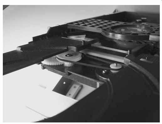
FIG. 1 Door mechanism on underside of platform
Clamp and Spindle Problems
A working door mechanism should take the disc in, plop it on the spindle and then lower the clamp onto it. Believe it or not, the only thing keeping the disc in contact with the spindle is friction. The clamp contains a magnet that's attracted by the metallic spindle, holding the disc in position and facilitating the friction grip.
Portable players rarely have clamps. Instead, three or four spring-loaded ball bearings or tiny tabs in the spindle grab and hold the upper edge of the disc after it’s pressed down firmly. I've never seen one of those be a problem.
In door-type players, improper disc clamping is common. The clamp's upper portion hangs loosely in its holder and should float when the disc is spinning. If the holder is misaligned, the clamp will rub against it, making an obvious noise and dragging the disc speed down, perhaps preventing playback. Don't be surprised if the clamp wobbles at the top a bit without rubbing. That's normal. Rubbing, of course, is not.
Dirt on the spindle can keep the disc from sitting flat, leading to focusing errors and skipping. If it gets greasy, the disc may slip. Make sure the spindle is clean.
When the disc spins, it shouldn't wobble much. You may see some shimmering of the surface, but the edges should sit pretty flat. If it wobbles, try another disc, to be sure the first one isn't warped. Assuming a good disc, any significant eccentricity is caused by either a bent spindle shaft (unlikely in door-type players but more plausible in top-loading portables, because people have to press on it when inserting discs) or clamping problems.
Playback Problems
If the disc is properly seated but won't spin, the startup sequence of head positioning, disc detection and focusing has failed. In a door-type player, it should begin as soon as the disc is seated. In a portable unit, there's another element: the interlock switch.
When the lid is closed, a little plastic finger on it protrudes through a hole in the player's body, pressing on the switch. If the finger breaks off or the switch fails, the micro will never know the door has been closed, and nothing will happen. I've seen numerous bad interlock switches in these players.
Is the head all the way in toward the center of the disc? If not, there's a sled problem. Check that the rails are greased at least a little, and that the start position limit switch is okay. Sometimes the leaf switch gets bent just a tad and will still work, but not until the head is closer to the spindle than it should be. Focus will be achieved but the head won't find the lead-in track, and it'll just sit there until the machine gives up and stops.
Before going further, check that the lens is clean and not scratched. Portable players with exposed heads are especially subject to dirty and damaged lenses. The lenses in door-type machines are well protected from scratches, but they can still accumulate dirt. If the machine has been in a smoker's home or was installed in a kitchen, there may be a film on the lens, preventing proper focus. Even a protected lens could be scratched if the user tried one of those nasty cleaning CDs with brushes.
Getting to the lens in a portable is easy. Pop open the lid and there it is. Take a cotton swab and wet it with water. Don’t use alcohol! The lenses are plastic and will be destroyed by it. Blot most of the water from the swab with a tissue, so that it's damp but won’t drip water into the optical head. Wipe the lens gently and then wipe it again with a dry swab. Don't put pressure on the lens while doing this.
To clean the lens in a door-style player, you may have to disassemble the clamp assembly and remove it. Sometimes you can reach under it by bending a swab's head at an angle.
With the head at the starting position, the lens should move up and down as the player searches for proper focus. The lens is mounted on coils of very fine wire called voice coils, so named because the arrangement of a coil over a magnet is similar to what's found in a speaker. Current passing through the coils generates a magnetic field that interacts with a permanent magnet in the head, permitting the control system to move the lens toward or away from the spindle and up and down. During playback, the lens assembly floats on this field, bobbing and weaving as necessary to follow the disc's track. Look at the head from the edge of the disc and you'll see the lens. If it's not moving, there's a problem with the focus circuits or the cable to the head. Even with a dead laser, the lens should move a few times until the micro figures out there's no reflected beam.
If the lens doesn't move, the start-up sequence has not been initiated. There could be a digital control problem, or the door's leaf switch might not be signaling the micro that the door has been closed. The door motor may still be straining, but you might not be aware of it. In portables, check that interlock switch! If it doesn't tell the micro the door is closed, nothing will start.
Laser Problems
Is there a beam? Its side reflection will be red (except in a Blu-Ray player, where it'll be blue). In a CD player, the beam will look dim. In a DVD player, it's very bright.
If it's there, the laser is probably okay. It might still have problems, but at least you know it's not dead.
If there is no beam, you've hit on the trouble! Alas, most disc player failures are due to a bad laser. If the lens is moving but there's no light, the laser is probably shot, and you have just become the proud owner of a parts machine. To be sure, you can trace back from the diode and see if it's getting voltage. Laser diodes are driven by a few volts DC, and there's usually a tiny trimpot right on the head at the diode that'll help you find the right connections. If the DC is there but the beam is not, it's bye-bye laser and bye-bye player.
You may see two trimpots in DVD players. Many use two lasers, an infrared for playing CDs and a visible red for playing DVDs. If the machine will play one but not the other, one of the lasers may have died. Be sure to test the unit with the type of disc it won't play.
Even if there is a beam, it might be too dim for proper operation. It's hard to tell with a CD player, because most of the energy isn't visible anyway, but you can get a good idea by comparing the brightness to that of a good player. In a DVD player, the beam is so bright that often notice it right through the disc! If the beam shines and the lens moves, but nothing else happens, it may not be finding focus. Look on the board for a test point labeled "FOK" (yeah, I know), "FOC OK" or "FOCUS OK." Scope it. It'll change state (usually from low to high) when focus is achieved. If it doesn't, then something is preventing proper focusing.
If the disc starts spinning, focus lock is good. The rotational speed depends on where on the disc the head is positioned. At the start, the disc should spin a few hundred RPM. If not, there's a problem with the spindle motor. Either it’s mechanically gummed up, the motor is bad, or the driving circuitry isn't doing its job.
Hair, both pet and human, can wind itself around the spindle motor's shaft, even in the protected environment of a door-style player. Remove the disc and turn the spindle by hand. It should turn easily and smoothly. If not, check for hair. Sometimes the motor goes bad or its lubrication dries out. If the spindle offers significant resistance, there's a mechanical problem of that nature.
The optical head provides two functions: tracking and data extraction. To get data, tracking has to be working. Either or both of these can be affected by oxidation or corrosion of the head's ribbon cable connectors. After a dead laser, this is the second most common head-related problem. Laptop drives, for some reason, are especially prone to this issue. Pull the cable at the board end and look at its metal fingers.
If they're gold, wipe them with an alcohol-moistened swab. If they're silver, they probably have solder on them. These are the kind that cause the most trouble. With a magnifier, look for black pitting. Gently scrape it with the tip of an X-Acto knife and then use a swab to wipe away the tiny metal flakes. Clean with alcohol and reinsert. If there's a connector at the head end of the cable, do the same thing there.
Be aware that laser diodes are easily destroyed by static charges. Be sure you and your tools have touched ground just before you begin working on the cable. Reinsert the cable and check to see if proper operation has been restored. I've saved countless laptop drives with this procedure.
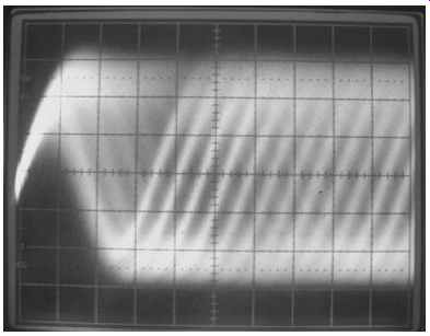
FIG. 2 Laser optical head eye pattern of a CD at a sweep rate of 100
ns. These are fast signals! Use 50 ns for DVD eye patterns.
The primary output from the head is a signal called the eye pattern. See FIG. 2.
This signal is the actual, raw data being read from the disc. All players have a test point at the first preamplifier stage, which you can find by following the head's ribbon cable back to the board. The preamp will be a chip of low to medium density, and you'll see test points very near its pins. Often they're not labeled, but you can find the eye pattern by scoping the points; no other signal will look anything like it.
The eye pattern should be around 1 volt peak-to-peak. If it's much less than that, either the player is not tracking well or the laser is dim. Some amplitude wobble is normal as the disc spins, especially when the head is near the outer edge, but it shouldn't be more than 15 percent or so. If the amplitude dips a lot, expect skipping or dropping out. Weak lasers can cause this, as can problems with the focus servo.
In players that have focus gain trimpots, you can sometimes compensate for a less than-optimum laser by upping the gain a tad. Most newer players don't have servo adjustments, but it's worth looking for a trimpot labeled "F GAIN" or "FOC GAIN," just in case.
If all looks well but the player skips, check for binding in the sled. If it's well greased and clean, with no hair in the gears, there might be a tracking issue. With power off, gently move the lens back and forth with a swab, checking that it moves freely. There could be dirt or hair there too.
Some players have tracking servo adjustments. Look for "TR GAIN" or "TRACKING GAIN" and try increasing it a little bit. The more hissing noise the lens makes, the higher the gain. You'll hear a "knee" above which the hiss will suddenly increase a great deal. Be sure to stay below that point or irregular tracking may occur.
If the machine is tracking the disc and the spindle is turning at the proper rate, there should be normal playback. Any other problems will be due to circuit failures that are probably more trouble to find than the machine is worth. Those kinds of problems are rare, though. Most players can be fixed with the procedures we've just examined.
Flat-Panel Displays
Unlike the old CRT technology, today's flat displays are matrixed. Each pixel, or picture element (a single dot), is addressed in X-Y fashion, so all of the circuitry required for scanning an electron beam over a screen is gone, and the associated service issues are different as well.
How They Work
In an LCD, a low voltage twists the molecules of a tiny bit of liquid-crystal material in each pixel, changing the orientation of its light polarization. In conjunction with a fixed polarizer at the front of the panel, that change of polarization darkens a pixel, making the pixel block the backlight's illumination. In a plasma display, a high voltage causes ionization of gas in each pixel, generating ultraviolet light that excites colored phosphors to generate visible light.
Today's displays have millions of pixels. A full HDTV display of 1920×1080 resolution contains 2,073,600 pixels, each with 3 subpixels of red, green and blue.
That's 6,220,800 tiny dots, and every one has its own connection! How are all those addressed? There aren't millions of wires coming out the back, after all. The process works somewhat as it does with memory chips: row and column addresses are sent through decoders that fan out to the appropriate connections, eventually reaching each and every pixel through transparent, printed conductors at the edge of the glass.
Using a grid formation allows far fewer connections than there are pixels; those 2 million pixels require just 6840 lines (1920 dots × 3 colors, plus the 1080 lines to select the rows). At the edges of the panel, the decoder chips make contact with the glass elements via ribbon cables affixed with pressure and conductive glue.
Virtually all LCDs made today are of the TFT, or thin-film transistor, variety.
Instead of addressing the LCD elements directly, the exciting voltage pulses a transparent transistor behind each element. That enhancement lets the pixel store its state after it's been addressed, resulting in much higher contrast than if it only got pulsed and then left alone until the next frame of video came along.
Printing millions of functional transistors over the area of an entire screen requires very high-precision manufacturing. In the early years, TFT LCDs suffered from bad pixels; most had a few, and it was considered normal. Today's displays rarely ever show any stuck pixels. Nearly all panels, LCD or plasma, are 100-percent functional. It's pretty amazing, really.
What Can Go Wrong
Loss of a single connection out of thousands at the panel's edge results in an entire row or column that won't darken, leaving a bright line across or down the screen.
Individual pixels can also fail, resulting in one dot of color that never moves on an LCD or a dark spot on a plasma. Plasma sets burn their phosphors when bright images don't move for an extended period, reducing the brightness of the affected pixels and leaving a ghost of the offending image. That happens most often with panels used for static display of airport schedules and such, but it also occurs at home with extended video game play and TV network "bugs," or logos, at the bottom of the screen.
The fluorescent backlights in LCDs are driven by inverters producing a fairly high voltage. They're just like the inverters in laptops, only bigger. Since the illumination provided always has to be as bright as the brightest picture could get, the inverters run pretty hard and hot, and are failure-prone. Some new sets use LED backlighting, eliminating the inverters. Those should last a good long time.
The high-voltage-generating circuitry in a plasma set also works very hard. Plasmas run rather hot, too, so they're more likely to experience thermal breakdown.
The power supplies providing the low-voltage, high-current power to run all this also generate some significant heat, leading to shortened component life and failure.
Is It Worth It?
If the panel develops a bad row or column, forget it. There is no way to repair that.
I fixed a few early LCDs by making a plastic clamp to squeeze the ribbon cable's conductors against the glass, but in today's higher-density panels they're inaccessible, and the size scale would likely make such a crude repair impossible anyway.
If the glass is damaged, you can't repair it. Plenty of today's TVs get hit by a kid's toy or the family dog, rendering the sets useless. The cost of a new panel is usually more than the price of the TV.
Electronic problems like bad power supplies, blown inverters and failing capacitors can be successfully navigated. Luckily, those account for most of what you'll see.
Computer monitors, especially, spend thousands of hours turned on, with the expected degradation of capacitors.
Dangers!
Plenty! In LCDs, watch out for the inverter and its output cables. They may have more than 1 KV on them. Plasmas are full of high voltage too, and it's fed to the panel's pixels, not just to a backlight lamp or two.
The actual liquid crystal material in an LCD is toxic and should not be handled.
You'd come in contact with it only if the glass were broken.
How to Fix One
In plasma sets, look for bulging electrolytic power supply caps and bad connections. A total failure might indicate a blown chopper or other typical switching power supply issue. Beyond those, much of the set is made of specialized, high-voltage parts best left alone, unless the trouble is in a small-signal area like the tuner.
LCDs also have the usual power supply and cap problems, but their most frequent cause of failure is the backlight inverter. If you're not sure what an inverter looks like, see Figure 10-5 in Section 10. LCDs of any significant size have at least two lamps driven by multiple inverter circuits, often combined onto one board with output transformers at the ends.
If you turn on the set and it lights up for a second before the screen goes dark, one of the inverters has died. You get that one moment of light because the other section is running its own lamp until the micro senses the loss of the blown one and shuts them both off a second later.
The poor output transistors in an inverter work like dogs for countless hours, and eventually one of them shorts, taking the fuse on the inverter board with it. In most designs, each side will have its own fuse soldered to the board near the connector from the power supply or the microprocessor board. That's very helpful, because a blown fuse tells you which side of the board has quit. Try replacing the fuse first, even if just with a temporary arrangement employing two soldered wires, clip leads and a physically larger fuse of the same rating as the original. If you can't determine the original's rating, 3 amps is a reasonable value to try. Now and then you may find that the fuse has fatigued and failed but the rest of the circuitry is fine. If the lights come on and stay on, a new fuse is all you need. Be sure both lamps are working.
The screen should be at normal brightness and evenly lit. If one end is significantly brighter than the other, one lamp is still out, and it's quite possible that the transistors on the blown side of the inverter became open from the momentary surge current when they shorted. So, they won't blow a new fuse, but they won't work either.
Take a peek at the inverter's transformer. If you see a burned spot anywhere, the transformer's insulation is damaged and the coil has arced over, either from one winding to the next or from a winding to the core. The increased current draw from arcing usually pops an output transistor. Changing the transistor does you no good, since the transformer will just kill the new one. If you see no burns, the transformer could still have internal shorts or arcing, but it's less likely.
If the transformer looks okay, you can change the inverter's transistors if you can find some. Often, they're oddball output components that aren't easy to locate.
Sometimes you can substitute similar transistors, but they have to be a pretty close match, especially in their gain characteristics. Not enough gain will cause the transistors to run more in their linear region than fully saturated, and they'll get very hot and fail in a hurry. Too much gain can cause them to "ring," with the tops and bottoms of what should be a square wave having sine wave-like variations. That also puts them in their linear region and overheats them. If you do sub the transistors, scope their collectors or drains and compare what you see to the waveforms on the good side of the inverter.
If they look a lot different, those transistors are not a suitable match. As long as the waveforms look like they're turning on and off all the way, and the inverter seems to work, let it run for a few minutes and then turn it off and touch the transistors. They might be warm, but shouldn't be too hot to touch. Compare them to the good side.