AMAZON multi-meters discounts AMAZON oscilloscope discounts
<< cont. from part 2.
VCRs and Camcorders
Tape-based video recorders are complex machines with many interactions between their various sections. Servicing them can be fascinating and challenging.
How They Work
VCRs and tape-based camcorders, both analog and digital, record very high-speed signals using the helical scan method, in which the tape is wrapped around a rotating drum, also called a cylinder. Protruding slightly from the drum are two video heads that scan the tape in a diagonal pattern, laying down very thin tracks next to each other, efficiently utilizing the width of the tape as well as its length to pack in lots of information. Helical-scan recorders are some of the most mechanically complex consumer devices ever sold. As a dying technology, they're cheap now, but their high cost in the early years of home video recording was not from price gouging. The mechanical precision required in their manufacture, especially of the head drum and heads, was in the microns. Those babies were hard to make! It took 20 years of research and development to bring VCRs to the masses, and their eventual low cost was due only to the economy of scale.
Analog recorders are more electronically complicated than their digital counterparts.
First, the amplitude variations and noise inherent in weak, fast signals coming from tape necessitate the use of FM recording. The video signal is used to frequency modulate an oscillator, and the resulting RF signal is then recorded. On playback, FM demodulation extracts information only from the frequency variation of the carrier signal, ignoring noise and wobbling amplitude. As with FM radio, the technique permits an inherently noisy channel to provide a clean signal.
TV signals are extremely time-sensitive, and no mechanical system can recover them from a recorded tape without timing errors rendering them from wobbly to useless. So, correction schemes involving phase-locked loops (PLLs) and, much later, digital timebase stabilization were developed. Color was especially difficult to reproduce, as even nanosecond-level jitters would wipe it out. A double PLL system- one for gross errors and one for fine adjustment-finally solved that problem.
Tape isn't perfect; it has microscopic areas where the magnetic oxide flakes off or is damaged by dust. On playback, the signal randomly drops out for very short periods as the heads lose contact with the tape. In an audio recorder, such dropouts are too small to be heard, and they also don't extend across the width of the entire track, so they have no effect beyond slightly increasing the noise level. With the dense, narrow tracks of helical recording, dropouts trash entire lines of video. The dropout compensator, an analog delay circuit storing a line of video, fills in missing lines with the previous one, rendering most dropouts invisible.
Digital helical machines only need to get bits on and off the tape, and they tolerate and correct timing errors by reading the data into memory and then clocking it back out steadily before converting it to an analog output signal. So, the timing correction systems in analog machines aren't needed, and a simpler PLL system suffices. The data rate is quite high, however, and dropouts are still a problem. Digital error correction codes are used to calculate missing bits and fill in for what gets lost.
The MiniDV format uses image compression similar to that in a JPEG, converting each frame to its compressed form and recording it separately. Newer formats using MPEG-2 or MPEG-4 compression periodically record key frames, which are complete frames, and then store only the changes between frames until it's time for another key frame. This more advanced technique results in far fewer required bits for a given picture quality level, but it's less suitable to tape recording because lost bits can affect many frames, not just the one in which they occur. MPEG recording is used in virtually all card-style and hard drive recorders, though, because recovery of all the bits is pretty well assured, and its higher storage efficiency is crucial. A few MPEG tape camcorders have been marketed, but they've never caught on.
In both analog and digital recorders, servos are used to control tape and head drum motion. In analog recording, the heads are time-aligned with the video frames by a head drum servo system to avoid having the machine switch from one head to the other during the frame. If you've ever rolled the vertical hold on a TV while playing a tape, you've seen a line of distortion just above the vertical sync bar. That's the switching line, where the machine switched between heads while recording. Imagine that in the middle of the picture! Without a servo to keep it near the sync and off the screen, the ugly line would wander through the frame.
To keep the heads centered on the tracks during playback, either head drum rotation or the tape motion through the machine must be controlled. Most VHS machines lock the heads to a crystal to keep their rotation steady, and control the pulling of the tape with a capstan servo, positioning the tape tracks under the heads as they fly by. It can also be done the other way, keeping the tape speed steady and adjusting head rotation, and some recorders use that method.
In VHS, the video track position on the tape is sensed using a control track of pulses recorded along the edge of the tape, one pulse for each head drum rotation. Newer formats like 8mm, Hi-8mm and MiniDV use signals recorded into the helical tracks themselves, and have no separate control track. While early VHS recorders sported manual tracking controls, modern units discern the correct setting automatically, taking a few seconds to find the best alignment. Later formats without control tracks lock up much faster. However it's done, the servo must center the rotating heads over those tracks for playback to occur, and servo problems are frequent causes of helical recorder failures.
The mechanical sections of VCRs are much like those of any tape recorder, except for the necessity of pulling the tape out of the cassette and wrapping it halfway around the head drum. This looks easy, but doing it reliably without damaging the tape was one of the greatest obstacles in the development of video cassette machines.
Loading problems are also frequent repair issues, especially in camcorders, with their tiny mechanisms that get tossed around in normal use.
The rest of a VCR is a TV receiver, with a tuner, audio and video sections. Early machines recorded audio along the tape's upper edge in linear fashion, like any analog audio recorder. The hi-fi system added frequency-modulated carriers for audio, recording them with rotating heads on the drum, along with the video tracks. All VHS hi-fi machines still record a monaural, linear audio track for compatibility with non hi-fi units, but later formats never included one.
The rest of a camcorder is a video camera, typically with a motorized zoom lens, autofocus and all kinds of signal processing. Modern camcorders, both analog and digital, use digital signal processing in their camera sections, eliminating all the trimpots and wads of circuitry used in older analog designs.
What Can Go Wrong
Most VCR and camcorder problems result from mechanical issues with the loading mechanisms and tape drives. Clogged video heads are common, and cleaning them requires care and a gentle, steady hand.
The tape has to be taken in, properly seated and threaded around the head drum.
Broken nylon gears are typical in VHS machines. Bent cassette carriages and loading arms cause a lot of camcorder failures because the parts are small, thin and easily deformed.
The tape path gets dirty from tape oxide residue and periodically must be cleaned.
The tension arm with its felt band around the supply spindle, from which the tape is fed, often gets bent just enough to misalign the tape path around the heads. That path is critical and tough to realign.
Video heads wear out, making proper tracking increasingly difficult and unreliable.
In analog recorders, the drum spins at 1800 RPM. In a MiniDV machine, it zips along at 9000 RPM. So, for each second of operation, those heads are seeing a lot of tape! It's a wonder they last as long as they do. It takes years of frequent use to wear out VHS heads and at least a couple to grind down MiniDV heads.
The entire machine's operations are directed by a microprocessor with many inputs. Various parts of the loading mechanism report back to the micro via leaf switch, mode switch or optical sensor so it can move them in the proper sequence.
The micro also keeps tabs on whether the spindles are moving and if the head drum and capstan motor are rotating at proper speed. A fault in any of these areas can trigger a shutdown. Those protections are a legacy of the early videotape years, when recorders, video heads and even the cassettes were quite expensive.
Is It Worth It?
VCRs are obsolete and cheap, but you might try to save one because you have tapes you want to continue to be able to view. Perhaps you even have a Betamax and some priceless home movies from long ago you need to dub to a DVD recorder. Camcorders range from throwaways to very expensive pro or semipro machines, so some of them may be more worth the effort to repair.
If the heads or other mechanical parts are worn out or broken, forget it, at least with VCRs and low-end camcorders. As with CD and DVD players, sources for video recorder parts are gone because they'd cost more than the machines they fit, if you consider the price of labor to change them. Service shops can still get camcorder parts, but it's unlikely you'll have access to them.
Heads are easy enough to clean, and tape path realignment of analog recorders, while something of an art form, can be achieved with a known good tape, a steady hand and an oscilloscope. Alignment of a pocket-sized digital camcorder's path is pretty nasty, because it's unlikely you can get to the required signal's test point without specialized factory equipment. I've had some luck doing it by trial and error, carefully noting the extremes at which picture blocks appeared and then setting the tape guides to the middle of the range.
Dangers?
The rotating head drum is easily damaged, and it can cut you if you contact its edge while it's whizzing around at full speed. Beyond that and keeping your fingers out of the way of the loading gears and such, there isn't much to worry about besides the usual power supply stuff. If you're not working on the supply, cover it to avoid inadvertently touching hazardous voltages.
How to Fix One
Let's look at some of the most common problems and how to solve them.
Stuck Tapes
If a tape is stuck in the machine, don't tear it out or you'll do more damage than you were trying to fix in the first place. Stuck tapes mean either a power supply problem or a mechanical failure. Most of the time, the rubber wheel driving the spindles has dried or worn out. Sometimes that results in a tape spill, and loops of tape can get wound around the guides and loading arm. If you rip out the tape, you'll probably bend or break those parts, and that's the end of the recorder.
Many machines use a belt to drive the wormgears that raise and lower the cassette carriage. Some also use one to move the loading arms that pull the tape from the cassette and wrap it around the head drum. When the belt stretches with age, the mechanism gets stuck and the micro goes into protection mode, shutting down the machine. VCR belts and wheels, once readily available, are fast disappearing. You may be able to retrofit a part from another machine. It's tempting to try a rubber band, but those stretch too much to be useful. The loading functions aren't so exacting, though, that a belt close in size but not a perfect fit might not work.
Take a look at FIG. 5. Before trying to remove a tape, check the position of the loading arms. Are they retracted, with the tape not protruding from the cassette shell? That's the best-case scenario. If you're lucky enough to find that, hunt around the sides of the cassette carriage for the loading motor and wormgear. Look for a belt from the motor to the first gear. With all power disconnected, try turning the gear by hand. If it won't turn one way, try the other. In one direction, it should begin to eject the tape. Keep turning it until the cassette can be removed normally.
If the loading mechanism is engaged, with the arms out in the threaded position or any position past fully retracted, you have a bigger problem. Sometimes the loading arms are properly retracted but the tape is out of the cassette anyway, because the spindles didn't turn to take it up while it was being unthreaded.
===
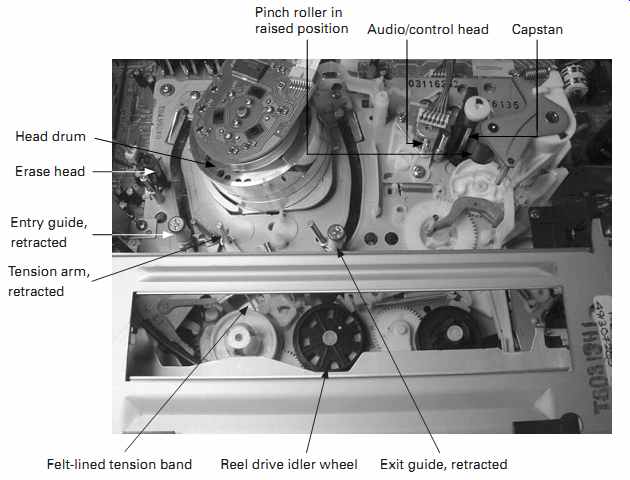
FIG. 5 VHS transport mechanism
Pinch roller in raised position Head drum Erase head Entry guide, retracted Tension arm, retracted Exit guide, retracted Felt-lined tension band Reel drive idler wheel Audio/control head Capstan
===
Either way, the problem is the same. While you might be able to remove the cassette with the procedure I just described, it's unlikely you'll get it out without destroying the tape. That's no biggie if it's just a recording of some old TV show, but if it's your only record of little Jenny's first birthday party, you don't want to lose it! Once videotape is creased or stretched, there is no way to flatten it back out and get a picture off of it. And if the damage is severe, running the bad spot through a machine later on may clog the heads every time you try it, making it hard to play the rest of the recording.
If you don't care about the tape, just cut it away and pull the shreds out of the mechanism. Then use the manual gear-turning procedure to eject the cassette. If the tape does matter, it's worth trying to remove it intact.
If things got stuck with the tape threaded, it may already be damaged, but at least you can try to avoid causing further carnage. Skin oils ruin videotape, so don't touch it with your bare hands. Put on a pair of fresh disposable rubber gloves, being sure to use a type that is not covered in talcum powder or lubricant of any sort. Try to extricate the tape from the mechanism as gently as you can. If there's grease along the bottom of moving parts, where they contact the chassis, be especially careful not to let the tape touch it. Playing a greasy tape can wreck a video recorder, and cleaning the grease from the tape is pretty much impossible without causing serious damage to its recorded contents.
During play, the tape is held against the rotating capstan shaft by a rubber roller called the pinch roller. Mechanisms that lower it from above make removal of tapes without damage especially difficult if the roller is in its lowered, ready-to-play position. To get a tape out of one of those requires manually turning the loading motor assembly's first driven gear by hand, just as with the cassette carriage motor, until the loading mechanism unthreads and retracts. The pinch roller will rise, freeing the tape.
Look for the loading motor on the underside of the tape transport chassis. I've seen a few on top, but not many.
Once you've extricated the tape from the mechanism, you need to turn either of the spindles to take it up before you attempt to eject the tape. It's a good-old catch 22: you can't reach them with the cassette in place, and you can't remove the cassette until you turn them. Place the transport on its side. On the back you'll see a pulley positioned between where the two spindles are on the top side. Usually, it's driven by a long belt from the capstan motor, though some fancy models use a separate motor to turn it. Try to turn it by hand, watching the cassette's reels to see when one is turning the right way to take up the tape. The supply reel, on the left, should turn counterclockwise. If the takeup reel, on the right, turns instead, it should go clockwise. Turn the pulley while carefully guiding the tape with your other hand, keeping it away from grease and from getting caught on the mechanism. When it's fully wound into the cassette, eject it by turning the carriage motor's gear.
If the tape is damaged, which is likely, avoid playing that spot on another machine, lest you wind up with another repair job on your hands! It's best to start playback after the damaged area.
Why Did It Happen?
Once you've gotten the tape out, check for why it got stuck in the first place. The cassette itself won’t cause this problem unless it has a label on it that peels off and jams the machine. Most of the time, stuck tapes are the recorder's fault.
Typically, the rubber wheel driving the spindles has lost friction. If that long belt on the underside has stretched or gotten dirty enough to slip, it'll cause the same problem.
The telltale symptom is that the mechanism has properly retracted but the tape is still out of the cassette. Machines with bad belts or wheels often have trouble rewinding, too.
Although replacement parts are hard to find these days, it may be possible to save the old one. Try cleaning it with a swap moistened with a small amount of naphtha. Don't saturate the swab! Just a drop or two will do it. Also clean the mating surfaces of both spindles. Let everything dry for a minute or so, and then turn the pulley on the other side of the transport while holding whichever spindle tries to turn. See if there's a good grip. Turn the pulley the other way and test the other spindle in the same fashion. If the repair is successful, don't expect it to last for years. Once the rubber wears out, there's no keeping it alive for a long time. It might see you through dubbing some tapes, though.
Other Loading Problems
The accepting, loading, unloading and ejecting of tapes are coordinated by the unit's microprocessor. Each process requires several steps, and the micro has to know where the mechanical parts are to perform the required sequence successfully. Buried somewhere in the mechanism, usually on the underside, is a mode switch with multiple contacts that connect when various parts of the mechanism reach their destinations.
Most mode switches are rotary, with fingers that rub against a set of printed-circuit contacts. Some are slide switches. Look for a bunch of wires or a ribbon cable going to the switch.
Dirty or oxidized mode switch contacts will seriously confuse the machine, causing all manner of odd mechanical behavior, from random shutdowns to stuck loading arms and out-of-sequence movements that ruin tapes. A little contact cleaner spray into the switch often does wonders. Just be careful not to let it get on the rubber parts or it will lubricate them too much for proper traction, and you'll have to clean it off. After spraying, run the mechanism through its loading and unloading paces at least half a dozen times to help the spray clear the dirt.
Cleaning
Any time you service a tape recorder, audio or video, clean the tape path. A dirty path will cause symptoms ranging from snowy playback to none at all. Even if playback is okay, clean the machine anyway. Helical recorders are especially prone to problems from tape oxide and other dirt because the alignment of the tape with the head drum is critical down to absurdly small tolerances. As gunk builds up along the drum's track, the lower edge on which the tape rides, it forces the tape slightly upward, disturbing the alignment and causing mistracking. Also, the contact surface of the video heads themselves is very small, and it doesn't take much to come between it and the tape.
Any loss of contact results in nearly complete loss of signal.
To clean the tape path, you'll need some swabs, isopropyl alcohol and a sheet of white printer paper. Dip a swab in alcohol and clean the loading guides that pull the tape out of the cassette and around the head drum. Pay extra attention to the ends against which the edges of the tape rub. Those get the dirtiest and are also the most alignment-critical. Then clean the tension arm and the erase head, on the left. Next, clean the stationary audio/control head on the right, the capstan and the pinch roller. Once you've cleaned the roller, throw away that swab.
That's the easy stuff. The head drum is the most delicate part of the machine, and cleaning it without doing damage to the heads, also called the head tips, requires extra care. Turn it slowly from above while you look at the slit where the rotating section meets the stationary base. As it turns, you'll see a small, rectangular-ish hole pass by. Sticking ever so slightly out of the hole is a video head. See FIG. 6. The head is very narrow. It's made of a strong but brittle ferrite material that can endure thousands of hours of high-speed rubbing against the tape. It cannot withstand much up-and-down pressure at all! If you push up or down on it, you will snap it off, and that's the end of the recorder. You'll find anywhere from two to six holes with heads, depending on how fancy a model the recorder happens to be.
To clean the drum, first dip a fresh swab in alcohol and clean the edge of the track, which runs diagonally along the bottom, from its highest point at the left to its lowest at the right. This is where the tape rides, and it needs to be really clean for proper tracking to be assured. Then clean everything between the track and the slit, carefully avoiding the video heads. (Rotate them out of the way as you go.) Once that's done, dip another swab and clean the rotating drum everywhere except very near the video heads or the heads themselves. Avoid those babies! Clean the drum by holding the swab and turning the drum against it from above, being careful not to get finger oils on the outer surface, which contacts the tape.
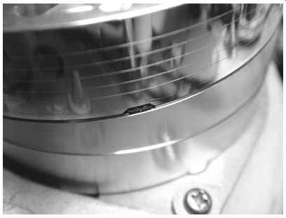
FIG. 6 Close-up of video head tip.
Now comes the fun part. Take the printer paper and fold it in half. Wet an inch or two of one side with alcohol. If alcohol is dripping from it, let that drip off, and blot the paper with another piece. Turn the drum so no video heads face you. Press the wet area of the paper against the drum, but not hard. Make sure some of that pressure is at the slit. Now turn the drum slowly so the video heads will rub against the paper as they pass by. Rotate the drum several times, being careful not to put pressure on the heads in an up or down direction. Remove the paper and let the drum dry. You should now have some black streaks on the paper and one clean VCR! Tracking Problems
If the tape doesn't track accurately, playback signal will be lost through part of the head's sweep across the tape, and you'll see snow somewhere in the picture, or the image will jitter vertically. There are several varieties of tracking maladies. If the machine won't track a tape it recorded, there's a loss of head contact from worn-out heads, dirt, misalignment of the entry and exit guides controlling the tape position on the drum or a lack of proper tape tension. Check the tape tension by gently moving the tension arm on the left. As you press it toward the left, the buzzing of the heads against the tape should increase significantly. As you push it right, the buzzing should get quiet. If tension is too low, there won't be much difference between its normal position and when you push it toward the right. The arm connects to a band wrapped around the left spindle. Between the spindle and the band is a coating of felt. The felt may be worn, or the mating surface on the spindle might be dirty. Clean the spindle's surface with alcohol and check again.
Sometimes the tension arm gets bent upward a little from pulling against the tape, so the tape doesn't sit properly on the guides. Gently bending it back may solve the problem. The tension arm should sit straight up and down. Bend it only if it’s obviously tilted. Even then, go very carefully, because it's easy to wind up with serious alignment problems if you get it out of whack.
If tapes made on the machine look fine but it won't play those recorded on other VCRs, there are two possible reasons: one of the guides may be off, or the position of the audio/control head may be incorrect. To test, play a tape recorded at the slowest speed on a VCR whose alignment you trust. Run the tracking through its range using the buttons on the remote (unless it's a really old VCR, in which case it may have a knob on the front panel). As the tracking shifts, snow will appear. If it's mostly at the top or bottom of the picture, and it moves up or down a lot when you change the tracking, it's a guide problem. If it appears across the entire picture at once, or nearly so, the audio/control head's position is off.
Adjusting the audio/control (a/c) head is easy. Set the machine's tracking control to the center of its range. On one side of the a/c head, you'll see a cone-shaped screw.
Turning it will move the head left or right without changing its tilt. Adjust the screw just a little. If the picture gets better, turn it some more, until the image looks good. If it gets worse, turn it the other way. Try not to turn it more than a few degrees either way.
Run the tracking through its range again and see if picture noise appears at approximately equal distance away from the center position. Adjust the audio/control head until that's the case. You should wind up with optimum tracking at or very near the center of the machine's tracking adjustment range.
Adjusting the guides is a much more involved affair. To set them, you need a tape recorded at the lowest speed on a machine you trust, as before. Put it in and set the tracking for the least snowy picture, even if one end has noise. Try to minimize the overall noise. It's better to have a strong picture with bad noise at one end than a slightly noisy image across the whole screen.
Warm up the oscilloscope and set it for 200 mv/div and a sweep rate of 5 ms.
Look for two cables coming out of the head drum, one from the top and one from the back. One of them will lead to a shielded area. It may be a separate metal box, or it may just be a shield over the circuit board. That's the video head preamp. On it or nearby will be some test points on a connector that has nothing inserted into it. Using the metal chassis as ground, scope the pins and you'll find a signal that looks like the upper waveform in FIG. 7. This is the RF envelope, an amplified rendition of what's actually coming off the heads. Connect your probe to it, being careful not to short adjacent pins with the clip. Scope triggering will be unstable, so the waveform will jitter from side to side.
To get a stationary trace, set the scope's second channel to 5 volts/div and the trigger to channel 2. Enable chop mode and scope some of the other pins on that connector until you find a square wave. Adjust the trigger level control for a stable sweep. You should now be able to see a rock-solid envelope, with the triggering square wave underneath. The envelope contains the signals from both heads, one after the other, and you can view the interruption between them at the point the square wave changes states.
The start of the head sweep, and thus of the envelope waveform, is on the left.
In the recorder, that corresponds to the entry guide just to the left of the drum. If the envelope is lower at the start of each sweep, that's the misaligned guide. Before you adjust it, take a good look at how the tape rides on it. If it's high, not touching the guide at the bottom, the tension arm may be bent upward a little bit, and you should gently bend it straight before trying to align the guide. Watch how the tape rides on the guide to get this correct. See FIG. 8.
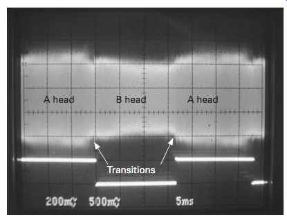
FIG. 7 RF envelope
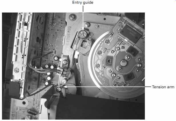
FIG. 8 Entry side with tension arm
If the waveform is low on the other side, the problem is the exit guide, on the right
To align either guide, you need to unthread the tape and slightly open the setscrew at the bottom of the guide, if there is one. Don't make it loose; you need some friction there. If there's no setscrew, you can proceed without worrying about it. Hit play.
When the tape is loaded and playback begins, turn the split screw adjustment at the top of the guide to lower or raise it. Tiny amounts suffice here; it's unlikely you'll need to turn it more than a few degrees.
The correct adjustment tool is a special split screwdriver made for the purpose.
Assuming you don't have one, you can use a normal screwdriver on one side, but be very careful that it doesn't slip off and whack into the spinning head drum. If it does, you'll probably break off a video head.
The two guides interact with each other and also with the track at the bottom of the drum. If the center of the waveform dips while the two ends do not, at least one of the guides is too low. Try to get the waveform as flat as possible. If there's some dipping at the ends, that's okay as long as it's not severe. Video recording uses FM, so no quality of signal is lost as long as the waveform stays above a certain threshold.
It'll wobble around slightly, because tape motion isn't perfect and we're dealing with insanely tight tolerances here.
As you adjust the guides, listen to the buzz of the heads hitting the tape. When the tape rides too low, the buzz increases quite a bit. The correct setting will be where it just starts to increase and sounds as stable as possible.
Unless the heads are badly worn, most of the adjustment issues will be at the start and end of the envelope, not in the middle. In particular, the entry guide side of the drum tends to have problems. To get a nice, close-up view of that transition, use delayed sweep to magnify just that portion of the waveform. Be sure to zoom back out afterward and check the entire envelope. Don't expect perfection; some amplitude variation between heads is normal. And the transitions will wobble up and down slightly. See FIG. 9.
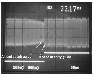
FIG. 9 Magnified view of head transition
Adjusting those guides is an art form that takes a lot of experience to do well.
Don't be surprised if you wind up going back and forth from guide to guide. The first few times I did this procedure were very frustrating. Stay with it, and you'll get the hang of it. If nothing works, and especially if the center of the envelope dips when the ends are correct, and you can't adjust your way out of that problem, the heads are probably worn out.
Digital Recorders
The ideas are the same, but the digital signal looks very different. You probably won't even find it in most camcorders. Your best bet is to take a tape from when the camera was new and use it as a reference, unless you have another digital camcorder whose alignment you trust. The tiny mechanisms in MiniDV camcorders bend easily, so check that the cassette is seated properly and the tension arm isn't bent. If necessary, carefully adjust the guides, watching for picture breakup instead of snow. Take note of the guide settings where it occurs and set them in the middle of the range. Use your ears to be sure the tape isn't riding too low. Also, if it's too high, the buzz will get much quieter. Find that magic spot, and you should have a good picture. Digitals use error correction and are pretty tolerant of data loss, so some misalignment gets masked, even though the drum and tape are smaller and the tolerances are tighter.
I've lined up a few digital camcorders using this technique, and they all work fine and interchange with each other well, even in LP mode.
Servo Problems
Helical recorders control both head and capstan rotation with servos. Mounted on each motor are PG coils, which are pulse generators. The coils pick up a field from a magnet in the rotating section, generating a pulse each time the magnet goes by.
This is fed to one input of the servo. The other input is a reference signal. The servo's job is to time-align the two by adjusting the motor speed and phase to match the reference signal's timing.
If a servo isn't working, the machine will mute, with no picture or sound on playback. You can verify a servo problem by scoping the RF envelope. If it has wild amplitude swings running through it randomly, the heads are not synced to the tracks because one of the servos isn't working.
Take a look at the tape reels. If they're moving fast even though the tape was recorded at slow speed, the capstan servo is out. If tape speed seems okay, look at the head drum rotation under a standard fluorescent lamp (not the spiral type). You should see a slowly creeping, almost stable pattern with a normal rate of rotation.
Listen to it too. If it's wildly off, the head servo is not working.
Servo operation is complex, but it's been reduced to a couple of chips. Many servo problems are caused by loss of signal from the PG coils or one of the reference signals. The one most likely to be troublesome is the control track pulse from the audio/control head. The control track is recorded along the bottom edge of the tape.
If you look at the face of the head, you'll see the upper and lower recording surfaces.
Make sure the lower one is clean. Sometimes wear, misalignment or low tape tension will cause the lower surface to lose contact with the tape, wiping out playback of the control track or making it intermittent. The machine will go in and out of servo lock, showing a picture and then muting repeatedly, especially near the beginning of a tape, when tension is the lowest. (A worn or stretched tape can also cause this symptom.) Use a dry swab to press on the tape's lower edge where it meets the head while a tape is playing. If the servo suddenly locks in, there's your problem.
One of the screws on the head mounting will control the zenith, or forward backward tilt. You should be able to deduce which one it is. Turn it to pull the top back a little, away from the tape. That'll put more pressure on the bottom and may restore servo operation. If you pull it back too far, the linear (non-hi-fi) audio track won't play, because the upper surface will lose tape contact.
If you really want to delve into the servos further, scope the PG coil pulses and follow their cables back to the servo circuits. Beyond that and some poking around with the scope, it's really not worth what it would take to hunt down obscure problems, given the value of the machines these days.
Color Problems
In analog machines, tape path misalignment can cause color distortion at the top or bottom of the picture by twisting or slightly stretching the tape, altering its timing characteristics as the heads read the signal. This usually occurs on the left side of the drum. You should be able to recognize such dimensional distortion visually and adjust the guide or correct the tension arm. Be sure to check the envelope after changing the tape path. You can do a quick-and-dirty check with the tracking control, watching for a reasonably even appearance of snow across the entire picture as you set the tracking away from its optimal point.
Color and luminance are processed separately in an analog video recorder and then recombined upon playback. The color subcarrier, 3.579545 MHz in the United States, is converted down to a much lower frequency before being fed to the video heads. On playback, it goes through a rather convoluted system of two PLLs that corrects the timing errors before it's mixed back into the monochrome part of the signal. If the machine plays back only in black and white, first be sure the tape you're using has properly recorded color on it. Then look for the 3.579545-MHz crystal on the board. Sometimes it's labeled 3.58. Make sure it's oscillating. You should see another couple of crystals near that one, so check their operation too. One of them is used only while recording. If you see no signal on it, put the machine into record, using another tape to avoid wiping out your test tape, and see if that crystal runs.
Audio Problems
The linear, non-hi-fi track is recorded along the top edge of the tape exactly the same way as in any audio tape recorder. The hi-fi tracks use FM subcarriers and are recorded right on top of the video tracks by an extra set of heads in a VHS machine. In Beta and 8 mm formats, the signal is mixed with the video carrier and recorded by the same heads that lay down the video tracks. In MiniDV camcorders, the audio is encoded into the bitstream along with the video data and recorded by the same heads as well.
Loss or breaking up of hi-fi audio tracks is usually due to dirty heads or mistracking.
Significant mistracking can occur around the vertical sync area of the signal, off the screen. Usually that'll cause vertical jitter, but sometimes it's placed just far enough from the vertical sync to avoid affecting the image. It'll still make a mess out of the hi-fi audio, though. Check the RF envelope. If it looks okay, try cleaning the video heads again; one of the hi-fi audio heads may still be dirty.
Dropping out of MiniDV digital audio usually means misalignment or dirt in the tape path. The format covers missing video blocks pretty well with blocks from the last image, so it may be masking loss of data, but the audio will still mute.