AMAZON multi-meters discounts AMAZON oscilloscope discounts
Once you've found a component you want to test, or one that's obviously blown, you need to remove it from the board. Back when all components were mounted on leads pushed through holes in single- or double-sided circuit boards, removal was easy. A little solder wick or a pump of the solder sucker, and the holes would clear. After that, all you had to do was pull.
Sometimes the process is still like that, but now there's much more variety of component styles requiring different removal techniques, and multilayer boards have complicated the situation. Component removal ranges from trivial to maddening, and it's easy to destroy the circuit board when a recalcitrant part simply refuses to budge.
Unless both sides of the board are accessible, you'll have to remove it from the unit before you can desolder anything with leads poking through the board. Either way, first make sure power is disconnected. I always look at the AC plug before beginning to unscrew a board or desolder components, just so I know the plug is definitely lying loose. Even if I remember having pulled it, I take another look.
Through-Hole Parts
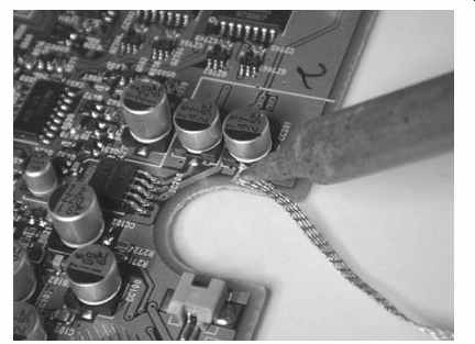
FIG. 1 Using solder wick.
Many larger components still use the old wire-through-the-hole mounting technique.
To remove power transistors and other through-hole parts, the solder must be sucked out of the hole, or the lead has to be pulled out while the solder is molten. Clearing the hole is preferable. For small joints, use solder wick, as described in Section 6.
Place the end of the wick on the joint you want to desolder, and then press the iron's tip on the other side. Hold it there for about 20 seconds, and the solder should flow up into the wick. See FIG. 1.
This doesn't always work, though. Sometimes the solder won't flow well enough to clear out the hole. The usual reason is insufficient heat, but transferring the heat to the joint is an issue too, as is thermal absorption by large copper lands. If you can't get a small land's hole to clear, try adding some fresh solder, and then wick it out again.
Boards manufactured with lead-free solder don't desolder well. Adding leaded solder to a lead-free joint lowers the existing solder's melting temperature, making removal easier.
The wick absorbs some heat too, so it takes a hotter iron to desolder a lead than it does to solder it. Plus, to remove a lead requires wicking out all of the solder in the hole. With thick or multilayer boards, some of it may be a millimeter or more away from the heat source, making the solder hard to melt.
Desoldering is complicated by the increased thickness of multilayer boards and their extra heatsinking effect from internal foils contacting the copper coating inside the holes. Applying enough heat to wick the solder out can destroy the board.
To remove a stubborn lead from a multilayer board, it's best to heat one side while pulling the lead out on the other, and then clear the hole after the lead is gone. Even then, you may struggle with it and be tempted to reach for the big soldering gun.
That's too much heat for small boards, and it can deform them and break internal connections in multilayer boards, wrecking the device. See FIG. 2.
Large lands used for power supply and ground buses create a heck of a heatsinking effect. It can be quite frustrating trying to get them hot enough to melt and clear the solder. The big gun might be called for here, but it's still possible to trash the board because there may be other lines running over the big land inside the layers. Heating up the big land can break them or short them to their adjacent layers.
If a part won't come out no matter how hard you try, it's a lot safer to clip the leads and solder in the new part without clearing the holes. Clip the new part's leads close and solder them to the residual solder in the holes. You should be able to heat a hole enough to make a good joint, even if the solder at the far end of the hole never melts. If there's room, you can leave a little of the old part's leads and solder to those.
Sometimes you can't get to the leads to clip them. On most electrolytic caps, the leads are under the parts, unreachable with any tool. The easiest way out is just to chop off the component near its base with a pair of wire cutters. Then you can clip or desolder the leads easily.
Bigger joints with lots of solder can overwhelm solder wick, saturating it before much solder is removed. To clean out an entire large joint might require a foot of wick, which isn't cheap. These are jobs for solder suckers. After applying the sucker a few times, you should be left with only a coating of solder on the joint. A sucker won’t remove that, so finish up with wick.
As mentioned in Section 6, avoid using a spring-loaded solder sucker on static-sensitive components like CMOS chips and MOSFET transistors. The rapid release of the plunger can generate static charges capable of damaging those parts.
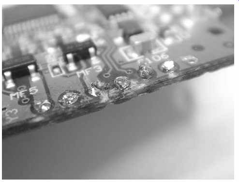
FIG. 2 How not to do it! Excessive heat destroyed this multilayer board.
Surface-Mount Components
Wicking surface-mount parts is easier because all of the solder is touching the wick, and many of the lands are very small and readily heated. Most surface-mount pads will desolder without incident. If the solder on a small land won't flow into the wick, try the same trick I described above: add some fresh solder to the joints before trying to desolder them.
Large lands on power supply and ground buses may still be hard to heat, but a normal iron will take care of most of them. Using a big gun on a surface-mount component is asking to destroy the part and quite possibly the board. Tiny SMT (surface-mount technology) resistors and capacitors have sputtered-on solder pads.
Too much heat can delaminate them, making reconnection to the parts' bodies impossible to achieve.
Most SMT components are glued in place before being machine-soldered at the factory. Very often, desoldering the ends of a part will break the glue and free the part, but not always. If you see a red shellac-like blob around the edges of the component, it's glued on and may not budge after desoldering. To move it, wick both ends and then heat one end while pushing on the component's body with a small screwdriver.
The tiny part may pop off suddenly and blast away into oblivion if you're not careful.
Somewhere in the universe there must be a room full of sad, homeless SMT parts that flew off circuit boards, never to be found. Plenty of 'em came from my workbench.
Choosing Components
Any time you need a new part, you just breeze on down to your local electronics supply store, buy the exact replacement and pop it in. Um, right, sure you do. Ah, if only real life could be like that! We don't even have local parts stores anymore. And while lots of standardized components are available via mail-order, many newer consumer electronics products aren't made from them. Instead, they're stuffed with all kinds of obscure and specialized components nobody but the manufacturer can provide. Luckily, in most cases you have a few options.
Junk Box
If you've stockpiled components, see if what you have is a close enough match. When using parts that have been sitting around for a long time, take some fine sandpaper to the leads to remove oxidation that will have built up. Otherwise, soldering to those leads will be unsuccessful.
Salvaging for Parts
There's a reason I've encouraged you to save boards from dead machines. Those from the same manufacturer as the unit you're repairing might use the same component, even if they're a different model. Manufacturers save costs by reusing parts of their designs and techniques in lots of models. If you can't find an exact replacement, you still might locate something close enough to work. Check all your parts machines, even those made by other companies. You're more likely to find a compatible part from the same type of machine, since the function is similar. So, if you need a part for a camcorder, check boards from those; you probably won't find what you need in a DVD player. If you locate something you can use, but the leads are too short, solder on a little wire to extend them.
Substitutes
Substituting a part with something close but not an exact match requires consideration of how the part is being used, what parameters are critical, and what you can get away with in a particular application. The general idea is that a part with better specs can sub for a lesser one, but not the other way around. Even then, there are exceptions.
Different component types have varying requirements. Let's look at some common ones.
Capacitors
Most of the capacitors you'll replace are electrolytics. Tantalum caps fail pretty often too, but they aren't used much anymore, so you may never run across one. The major factors in an electrolytic are its size, its capacitance, its voltage rating and its temperature rating. Also, switching power supplies and computer motherboards often require caps with especially low ESR, to smooth out the fast, sharp pulses those circuits produce. Replacing such parts with standard electrolytics will cause malfunction.
The most important consideration after size-it does, after all, have to fit on the board in the allotted space-is voltage rating. Electrolytics simply won't stand voltages higher than their ratings, at least not for long; they fail catastrophically by shorting.
Their life is reduced even by running them at voltages under but close to their ratings, yet some manufacturers will use a 15-volt part at 13 volts, leading to frequent failures.
In cases like that, a replacement with a higher voltage rating than the original part is not only okay, it's desirable.
The capacitance rating is not as critical as you might suppose. Most electrolytics have rather wide tolerances, in the range of -20 to +80 percent. If the cap is being used to couple signals from one stage to another, the capacitance value is more important than it’s when the part is a bypass or filtering cap. You might find a few electrolytic coupling caps in audio and video gear. In audio amplifier stages that use caps of a few microfarads from an emitter to ground, it pays to keep the value close to the original, because a higher value might increase low-frequency response, upsetting the audio quality.
You will see tons of electrolytics in power supplies and for bypassing and filtering in all kinds of products, from simple analog devices to today's most complex digital gear. Those are the parts that usually need replacement. If your available replacement's value is no more than 50 percent higher, go ahead and use it. A little extra filtering never hurt anything, and +50 percent is likely within the stated tolerance of the original part anyway. To be sure the new part isn't at its maximum tolerance value of, say, 80 percent over the stated value, measure it with a capacitance meter. Despite their wide stated tolerances, most electrolytics I've measured have been within ±20 percent or so of their printed values.
Combining capacitors to get near the needed value is fine in most applications. I don't recommend it, though, for the big storage cap at the input of a switching power supply (near the chopper), or in other high-voltage circuits. Putting caps in parallel adds their values, and putting them in series drops the final value according to the following formula:
Capacitors combine exactly opposite to how resistors do. For more info, see the section "Resistors" a bit later in the Section.
When putting polarized capacitors in series, be sure they connect + to -, so you wind up with one + and one - at the ends of the string. When you parallel them, connect all the + terminals to each other and all the - terminals to each other. In either case, be sure each capacitor's voltage rating is equal to the entire applied voltage. When in series, the individual caps won't really be subjected to the full voltage during normal operation, but a big voltage spike can occur when power is first applied, so it's a smart safety move to be certain every one of them can handle it.
Especially in power supply applications, the cap's temperature rating matters.
Electrolytics that get charged and discharged very fast, as they do in a switcher, can become plenty warm from the power dissipation of their internal resistance. Standard electrolytics are rated to operate at 85° C, with higher-temperature caps rated as high as 150° C. Manufacturers hate paying for things they don't need, so respect the temperature ratings if you want the repair to last. For quick testing purposes while troubleshooting, you can disregard the ratings because the part won't be running long enough to fail from overheating.
Tantalum capacitors should always be replaced with the same type. They have lower impedance at high frequencies than do standard electrolytics, and are used only where that matters. Replacing a tantalum with a garden-variety electrolytic will result in performance degradation or circuit failure. The capacitance tolerance of tantalums is much tighter than that of standard electrolytics, so use a part with the same value.
An increased voltage rating is fine, however.
Diodes
Diodes and rectifiers have four primary characteristics: forward voltage, reverse voltage, current and speed.
The forward voltage spec tells you how much voltage can be across the part in its conducting direction. You won't often see this specified, because in an AC circuit the forward and reverse voltages are usually the same. The reverse voltage is specified as PIV, for peak inverse voltage, and it tells you how much voltage the diode can withstand in its nonconducting direction. Exceed the PIV, and the part will arc over inside and be destroyed.
The current rating indicates how much current can pass in the conducting direction without overheating the part and burning it out. No current should flow in the reverse direction, of course.
The speed of a diode is very important in some small-signal applications like radio signal detection. It's also critical on the low-voltage side of a switching power supply, where the part will be rectifying the fast pulses from the conversion transformer.
In the sections of power supplies operating at the low frequency of the AC line, any rectifier is more than fast enough. The bridge or individual rectifiers at the AC cord side of a switcher are not high-speed devices; nor are the rectifiers on the low-voltage side of a linear supply.
When subbing a normal, low-speed rectifier or bridge, pay attention to the PIV and the current rating. As long as those are equal to or higher than the original part's ratings, the new part should work fine.
Look up high-speed rectifiers in a substitution guide or online. Replace them with parts of equal or better PIV, current and speed. Never replace a high-speed rectifier with a low-speed part, even if the PIV and current specs are fine. It simply won't work.
Some products use lots of glass small-signal diodes. Look for numbers like 1N914 and 1N4148. They're interchangeable. Even if you see no number on the diode, either of those numbers should work fine. Just be sure the diode you're replacing is in fact a simple diode and not a zener. There are some other special-purpose diodes, too, including germanium diodes (also glass but noticeably larger than normal silicon diodes), gallium-arsenide diodes, tunnel diodes, and varactors. They're found in receiver front ends and other weak-signal, exotic applications. You won't run into them very often, but they must be replaced with diodes of the same types.
Resistors
Many resistors are carbon composition types and easy to sub. What matter most are the resistance value and the power dissipation capability. It's fine to use a 1 percent precision resistor in place of a standard 5 percent one, and it doesn't hurt if the replacement is rated to handle more power.
If the original resistor was a special type, such as a wire-wound or low-noise part, it's important to replace it with the same type. Those kinds of parts are used only in special applications. You won't find them very often in consumer electronics gear, but they show up now and then in switching power supplies, preamps and stages handling particularly small signals, like receiver front ends.
If you can't find the exact value you need, consider the original part's tolerance (see Section 7), and try to combine a few other resistors to get to a value well within the original part's specs. For instance, if you need a 3.3 k-ohm resistor, you could put a 2.2 k-ohm and a 1 k-ohm in series. Resistor values in series add together, so that'd get you to 3.2 k-ohm. If the original resistor had a 5 percent tolerance, as most do, it could vary by ±165 ohms and still be okay. So, 3.2 k-ohm would be fine as long as the combined resistors' own tolerances didn't push their total value outside the tolerance range of the original part. Check the real value of the combination with your DMM to be sure.
Resistors in parallel combine opposite to how capacitors do. The resistance value goes down according to the formula shown here:
Two resistors of the same value will produce half the resistance. The larger the resistance of the second resistor, compared to the first, the less effect it has on it.
Play around with a few resistors by combining them in parallel and measuring them, and you'll get the hang of it.
Transistors
Transistors are the most complicated parts to substitute. Major semiconductor manufacturers used to give away large transistor substitution books filled with hundreds of pages of transistor types and their brands' appropriate cross-referenced substitute part numbers. Because many types of transistors have similar characteristics, a few hundred parts can sub for thousands of parts.
These days, you can look up this stuff online, but you may run into numbers for which you can't find a cross, or there might be a valid sub but you can't get one.
Alas, some parts are still made of unobtainium. Even when a substitute component is available, you may prefer to speed up the repair process by using a part you already have.
To choose your own substitute requires some understanding of the part's application and how a change in characteristics would affect circuit performance. Some functions, like simple switching of voltage to direct it to various circuit stages or turn an indicator on and off, will work with just about any transistor of the same basic construction (bipolar or FET) and polarity. Others, such as high-frequency signal processing or current amplification in complementary output stages, often require stringent adherence to the original part's specs.
All this assumes you know the old part's number. Usually you will, but at times you might have to fly blind. If the original transistor literally blew apart, which occasionally happens when a heck of a lot of current has been pulled through one, there may not be a number to read! I've seen SMT output transistors in LCD backlight inverters blow so hard that there was little left between the solder pads. Even when the number is visible, it could be a proprietary house number, with no cross-reference to a sub. And some transistors, especially tiny SMTs, show no numbers in the first place.
If you're lucky, the board will be marked with ECB or GDS, showing what terminal goes to which pad. ECB indicates emitter, collector and base, thus a bipolar transistor.
GDS means gate, drain and source, the terminals of a FET. Those markings also give you strong clues to the part's polarity. If C goes to the positive side of things, it's an NPN. If E does, it's PNP. With a FET, if D is positive, it's an N-channel part. If S is positive, it's P-channel.
Without board markings or a part number, the transistor is a total mystery. Use your scope and understanding of basic transistor operation to deduce the part's polarity and layout of connections. Start by looking for the power supply voltage feeding it. If it's positive and fed through a resistor or a transformer, you've probably found the collector of an NPN transistor or the drain of an N-channel FET. Find the stage's input by looking for whatever signal operates the transistor. If it's a continuous signal, you should see it. If it's something that happens only when you press a switch or some other operation signals that area of the circuit, create those conditions and find the signal. When you find it, you've found the base or the gate. Whatever's left will be the emitter or the source.
Most bipolar transistors are NPN. If the connection to the positive supply line is direct, without a resistor, or there is a resistor but it's of very low value, the transistor could be PNP, and that connection would be its emitter. Find what looks like the base by scoping for signals. See if there's a resistor from the base to the transistor terminal closest to the supply. PNPs are used to turn on and pass current from the supply to some other circuit when the input signal goes low, toward ground. The resistor going up toward the supply keeps the base high and the transistor turned off until the input signal pulls it low. You'll find PNP circuits of that sort in power switching sections of battery-operated products.
Assume the part is an NPN bipolar transistor, and you'll be right most of the time.
If your replacement turns out to be the wrong polarity, the circuit won't work, but it shouldn't do any damage.
All bets are off if the transistor is part of a complementary push-pull amplifier.
They use NPNs and PNPs in more complicated, hard-to-deduce ways. And if the original part was a FET, the issues of enhancement and depletion mode, and JFET versus MOSFET, make the whole thing very tough to fathom. Getting the identification correct requires your understanding how those parts work and looking at the bias on the gate terminal to infer what the output should do as the input changes.
Don't try to sub chopper transistors in switching power supplies without knowing the correct part number and finding a legitimate sub from a cross-reference. Most choppers are power MOSFETs with specs that must be closely matched for reliable operation. Even if a sort-of-close sub works, it probably won't run for long before failing. Sometimes even a legit sub will die in a hurry, and the only part that will work is an exact replacement of the original part number. The same is true of horizontal output transistors in CRT TVs, another application involving fast pulses at fairly high voltages and currents.
In some cases, the original and replacement transistors are electrically compatible but their arrangement of leads, called pin basing, is different. Most small-signal American transistors are EBC, left to right, while Japanese parts are usually ECB. You can replace one layout with the other as long as you switch the two leads, being careful not to let them touch as they rise from the board toward the transistor. Small FETs are usually SGD. Power transistors are usually BCE, with C connected to the metal tab (if there is one), but check to make sure. Power FETs typically use GDS, with D connected to the tab.
Once you've figured out what should go where, whether from the original part or from scoping and deducing, you can proceed with trying out a new part. The primary characteristics to be concerned with are gain, high-frequency cutoff point and, with larger parts, power dissipation capability. Secondary characteristics, but still very important, are the maximum voltages permitted from base to emitter and from collector to emitter.
Very often you'll find a transistor that's pretty close but has a little more or less gain. Depending on the application, that might work. If the circuit is linear, producing output proportional to the input, the transistor isn't normally saturated (fully turned on), so a slight gain difference may not cause a problem. In switching circuits like backlight inverters, though, inadequate gain can result in lots of heat from the transistor's not-fully-turned-on resistance, burning out the part in a hurry. Too much gain in a linear circuit may cause distortion, increased output or spurious signals. Not enough usually just results in a bit less output.
The high-frequency cutoff point specifies at what frequency the transistor's gain will have decreased to one. In other words, it won't be amplifying at or above that frequency. In low-frequency applications such as audio, any transistor will be more than fast enough. At radio frequencies, the situation can be quite different, requiring a transistor whose cutoff frequency is approximately equal to the original part's spec.
Too little might result in low or no output, while too much could result in unwanted harmonics or spurious signals riding on the desired one. When in doubt, go for too much, as long as the difference isn't excessive; at least the thing will try to work.
Power dissipation is very important. The new part should be able to dissipate at least as much power as the old one. A better dissipation spec is fine.
Maximum permissible inter-electrode voltages must be respected. Exceed them and the transistor might emit some of that magic smoke. Most transistors' collector to-emitter specs are well beyond what a small-signal circuit produces. The circuit's base-to-emitter voltage, however, could exceed the capabilities of some replacement parts, so keep an eye on that. Large parts used in output stages can have pretty high voltages applied from collector to emitter, so don't take that spec for granted.
If all this seems overwhelming, stick to replacement part numbers from a cross reference guide or online source, and you'll be fine. Even with expertise, matching up transistors is very much a roll of the dice. See, I told you it could get complicated!
Zeners
The purpose of a zener diode is to break down nondestructively in the reverse direction and conduct when the part's reverse voltage spec, or zener voltage, is reached. The important specs are the zener voltage and the power dissipation. Unlike normal diodes, zeners' dissipation limits are specified in watts, not amps. Always replace a zener with one of the same zener voltage and at least as much dissipation capability. A higher dissipation spec is fine.
You can put zeners in series to add their voltages, but don't parallel them to increase dissipation capability; even zeners with the same zener voltage won't start conducting at exactly the same voltage, so one will always take more current than the other, resulting in its premature failure. When combining them in series, be sure that the wattage of each zener is at least as high as the original part's rating, and watch the polarity. Each zener should feed the next one cathode to anode, so you wind up with one anode and one cathode at the ends of the string.
Installing the New Parts
Once you've procured or substituted components, it's time to put them in! Proper installation is crucial for successful, long-term repair. Let's look at some issues specific to various kinds of parts.
Through-Hole
Replacing a through-hole component is pretty easy, requiring nothing more than pushing the leads through the holes, bending the ends a little so the part doesn't fall out, soldering the leads and then clipping off the excess.
If the part is attached to a heatsink, it's a little more complicated, but not much.
For a free-floating heatsink bolted or clamped to the top of the component, install the heatsink before soldering the part to the board. When the part mounts on a fixed heatsink, put the leads through the board's holes without soldering them, and then screw or clip the component to the heatsink. Solder the leads only after the mounting procedure is complete.
If the original part used heatsink grease, you need to do the same with the new one. The grease used is a special silicone compound formulated for maximum heat transfer. You can get it from online parts houses, and computer supply shops that carry CPU upgrades and bare motherboards also carry it. Most heatsinks, including those with mica or thin plastic insulators, do require the grease. Those with rubber separators usually don't, though. FIG. 3 shows typical insulator setups requiring thermal grease.
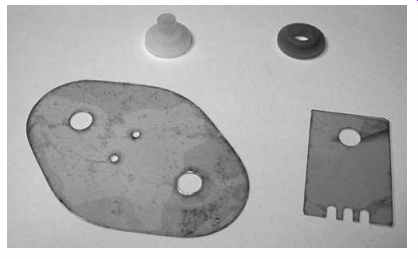
FIG. 3 Transistor mounting hardware with screw sleeves
A thin smear of the special grease on one of the mating surfaces helps heat transfer across the less-than-perfect contact area, filling in tiny gaps and increasing effective surface area. Too much grease can separate and insulate the surfaces, reducing heat flow, so don't overdo it. Smear on the grease with a swab, and be careful not to put bending pressure on the insulator or it may break. Mica insulators are especially brittle, and even a single crack can lead to a short later on. To avoid bending it, place the insulator on your workbench before applying the grease.
The insulator's job is to isolate electrical contact between the component and the heatsink while facilitating heat transfer. If there's no insulator, either the part has no contact point on its case, as with an all-plastic transistor, or it's okay for it to be connected to the heatsink. Voltage regulators sometimes have their ground connections on the metal tab, so contact with a grounded heatsink is a good thing.
Many power transistors, though, have their collectors or drains at the tab. Those are usually connected to voltage sources, and contact with ground would be a short. Insulators are used to avoid the connection.
When there is an insulator, and the component has a metal tab, the mounting screw will pass through a plastic washer with a sleeve. Be certain to use it, and watch its orientation. The sleeve should fit into the hole on the transistor's tab, preventing the screw from touching the inside of the hole.
Tighten the mounting screw more than you would a screw holding a board down or a case together. You want good heat transfer, and that takes some pressure. Don't overdo it to the point of breaking the insulator or stripping the screw, of course.
Occasionally, you will find a thermistor (a heat-sensitive resistor) glued to the case of a power transistor, especially in the output stage of a push-pull audio amplifier.
Thermistors are used to adjust the bias of bipolar power transistors as the parts heat up, because their gain and optimum bias point drift with temperature. If you can get the thermistor off without destroying it, glue it with epoxy to the new part. If you can't remove it, you'll need a new thermistor. Look up its part number and order one just like it.
SMT
Putting in a new SMT part is a bit tougher than installing a through-hole component, thanks to the size scale. How do you hold it in place long enough for soldering? Gluing is not recommended. Sure, the manufacturers do it, but they have special glue made for the purpose, and we don't. More than likely, some other line runs underneath the component, and a later attempt to remove the glue will tear the copper off the board.
Also, the electrical properties of the glue you might use are a wildcard; you have no idea how its presence might affect circuit performance. It could exhibit capacitance or even conduct current.
To get an SMT in place, first use wick to clean the board's solder pads so that there are no raised bumps of solder on them. You want the SMT to lie flat. Melt a little solder onto your iron's tip. Now place the part on the board and line it up carefully with a tiny screwdriver. Center it between the pads so it can't create a short across two lands. Hold down the body of the SMT with the screwdriver while touching the iron's tip to one end of the part. The solder on the tip should flow onto the board, making a joint at that end. Don't worry about getting a good joint; all you want to do is prevent the part from moving.
Once the component is held in place by the solder on one end, solder the other end properly. Then go back and redo the messy end. Take a good, close look with your magnifier to be sure you haven't created any solder bridges to adjacent pads or parts.
Finding Parts
Proprietary components have to be procured from the manufacturer (unlikely these days, but worth a try), the component maker who supplied them (possible) or a parts unit. For popular gadgets, finding a parts unit may be the easiest way to go. Check eBay.
Standard components are widely available through online mail-order, but many parts houses have minimums, so you might have to spend a lot more than the part is worth. Oh well, you can always stock your components supply with other goodies you might use later. Or, you can save up your parts needs until you have a big enough order. That'll delay your repair work a long time, though.
Here are some places to look for components:
RadioShack (radioshack.com) • This seller's parts variety is small, but the company offers a few transistors and chips, along with standard 5 percent resistor values and some electrolytics.
DigiKey (digikey.com) • This mail-order parts house has just about everything you could ever want. Its catalog is overwhelming, and you can download it as a PDF.
Mouser Electronics (mouser.com) • Another powerhouse, Mouser has a wide variety of components, including many used in consumer electronics devices.
All Electronics (allelectronics.com) • This is a surplus house with lots of interesting material at bargain prices. It has inexpensive, generic backlight inverter boards that can be retrofitted to LCD monitors, though the boards lack terminals for brightness control.
Do an online search and you'll turn up dozens more sources for both prime and surplus components.
Saving Damaged Boards
When you desolder a through-hole component, one unfortunate result of failing to get the hole hot enough is that its copper lining comes out with the lead. If you see what looks like a sleeve around the lead, you've torn out the copper. On a double-sided board, it's not a catastrophe. When you replace the part, be sure to solder both the top and bottom contact points, and all will be well. You might have to scrape some of the green solder mask coating off the top area to get contact between the lead and the foil. That's best done with the tip of an X-Acto knife.
Pulling the sleeve out of a multilayer board can destroy it because you have no way to reconnect with interior foil layers that were in contact with the sleeve. If you're lucky, that particular hole might not have had inner contacts, and soldering to the top and bottom may save the day, so it's worth a try. Don't be surprised, though, if the circuit no longer works.
If you can figure out where they go, broken connections can be jumped with wire.
On double-sided boards, it's not too hard to trace the lines visually, though you may have to flip the board over a few times as you follow the path. When you find where a broken trace went, verify continuity with your DMM, from the end back to the break.
Don't forget to scrape off the solder mask where you want to contact the broken line.
Wire jumping can help save boards with bad conductive glue interconnects, too.
On a double-sided board, you can scrape out the glue and run a strand of bare wire through the hole, soldering it to either side. Forget about trying this on a multilayer board, however; you'll probably trash it while trying to clean the hole. On those, it's best to run an insulated wire around the board from one side to the other. That adds extra length to the conductive path, which could cause problems in some critical circuits, especially those operating at high frequencies. At audio frequencies, it should be fine. If some interior layers are no longer making contact with the glue, this won't work. Most conductive glue boards I've seen have been double-sided, making them suitable for wire jumping.
If the board is cracked from, say, having taken a fall, scrape the ends of the copper lines at the crack. It's possible to simply solder over them, bridging the crack, but that technique tends to be less permanent than placing very fine wire over the break and soldering on either side. To get wire fine enough, look through your stash of parts machines for some small-gauge stranded wire. Skin it, untwist it and remove a single strand.
Sometimes there are multiple broken lines too close to each other for soldering without creating shorts between them. To save boards like that, scrape the solder mask off close to the crack on every other line. Then scrape the in-between lines farther away from the crack. Use the bare wire strands to fix the close set, and use wire-wrap wire (very thin, single-strand, insulated wire used with wire-wrap guns for prototyping experimental circuitry) or enamel-insulated "magnet wire" to jump the farther set. Wire-wrap wire is especially good for this kind of work because its insulation doesn't melt very easily, so it won't crawl up the wire when you solder close to it, exposing bare wire that could short to the repaired lines nearby. Plus, it's thin enough to fit in pretty small spaces. For even tighter environments, use the magnet wire. Just be sure to tin the ends of the wire to remove the enamel, so you'll get a good connection.
It's possible to repair broken ribbon cables in stationary applications (the ribbon doesn't move or flex), if they are the copper-conductor type of ribbons, not the very thin, printed style. Fixing cracks with wire is a tedious, time-consuming technique, but it works. Accomplishing it without causing shorts takes practice and isn't always possible with very small, dense boards and ribbons.
On multilayer boards, cracks and torn sleeves are extremely difficult to bypass. If you have a schematic, you may be able to find the path and jump with wire. Without one, it's pretty much impossible when the tracks are inside the board.
LSI
Back in Section 7, I promised to describe a trick for resoldering big ICs with very close lead spacing. Those large-scale integrated (LSI) chips with 100 leads are in just about everything these days. It's not likely you could find a replacement chip, so why would you want to resolder one?
With so many leads, an intermittent connection to an LSI is not uncommon. SMT boards are factory-assembled with reflow soldering, in which solder is applied to the pads and then reflowed onto the component leads with hot air, infrared lamps or in a special oven. Reflow soldering relies on low-temperature solder that can break after the numerous heating and cooling cycles encountered in a product's normal use. Now and then one connection out of an LSI's long row of them will go flaky. The leads are so close together that there's no way to apply solder to one without causing a short to the adjacent leads.
Here's the trick: go ahead and short them! With all power removed, of course, solder away and let as many leads get shorted together as you want. Once you have good solder on the problem lead, lay solder wick across the leads where the excess solder is shorting them. Heat it up and wick off the excess, but don't wait until the leads are bone-dry. Pull the wick off a little sooner. If you get the timing right, you'll be left with a perfectly soldered row, with no shorts. The wick soaks up the solder in between leads faster than what's underneath them (where you want it to stay).
If you wait too long and wind up removing so much solder that the connections to the board aren't solid anymore, resolder the area and do the wick trick again. After you try this procedure a few times, you'll get the hang of how long to wait before pulling the wick. I've had tremendous success with this approach. The one caveat is that it's hard to wick out solder if it gets under the edges of the chip. To avoid that problem, solder as far from the body of the IC as possible. That helps prevent overheating the chip, too.
When you're all done, use your magnifier to verify that the contact points with the board are soldered, and that no bridges exist between leads. Honest, it really does work! I've even replaced a few LSIs this way, using chips from parts units. Getting those babies lined up accurately on all four sides ... well, that's another story.