AMAZON multi-meters discounts AMAZON oscilloscope discounts
Now that you have the unit open and ready for diagnosis, it's time to apply the ideas we've been examining and put that oscilloscope to good use. Locating the trouble is the heart of the matter and much of the battle. The general approach is to reduce your variables to eliminate as much circuitry as possible, concentrate on what seems a likely problem area, take some measurements, apply a little logic, and gradually narrow your focus until you reach the bad component.
Where to begin? That depends on what symptoms are being displayed. In order from least functionality to most, here are some good ways to pick a starting point.
Dead
As we discussed awhile back, dead means nothing at all happens when you try to turn the unit on. If that's the case, head straight for the power supply. Check the fuse first.
If it's blown, assume something shorted and blew it. The short could be nearby, in the rectifiers, the chopper transistor or its support components, or it could be somewhere in the circuitry being powered by the supply, far from where you're looking.
If the supply feeds the circuitry through a cable, disconnect it. Replace the fuse and try applying power. Does the fuse blow again? If so, the problem is in the supply. If not, the fault could still be there, but more likely a short in the circuit being powered is drawing too much current and popping the fuse.
Some power supplies have small, low-current sub-supplies for standby operation, so they can keep enough circuitry alive to respond to remote-control commands or soft switches. The main supply turns on only when commanded to do so by the product's microprocessor. With the cable disconnected between the supply and the rest of the circuitry, the micro can't command the supply's main section to start up. If the short is in a part of the supply not running while in standby, the supply will appear to be okay and will not blow the fuse, confusing the matter of where the short lies.
If the fuse is not blown but the unit still does nothing, take a good look at the electrolytic capacitors in the supply and also in other areas of the unit. See any with even slight bulges on top? If so, forget about continuing your exploration until you've replaced them. By the time a cap bulges, it's pretty far gone, with perhaps 10 percent of its original capacitance left. Its equivalent series resistance (ESR) will be way up as well. Very likely, replacement of the bulging parts will restore operation of the unit.
If you don't see bad caps, check the supply's output voltages with your DMM. Find circuit ground on the output side (never on the AC input side of a switcher!) and hook the black lead to it. In a unipolar design, the negative output lead is almost always ground. If the supply is bipolar, there will be positive, negative and ground.
Even if the supply provides several output voltages, one ground serves them all, although multiple wires may be connected to it.
In a metal-encased product like a disc player or VCR, the metal chassis should suffice as long as you can find a spot that's not painted over. In a pinch, you can usually use the outer rings of RCA jacks in audio/video gear. Choose an input jack, not an output jack, so you don't risk shorting an output if your alligator clip makes contact with the jack's inner conductor.
Many supplies have markings for the voltages on the boards, right next to where the output cable plugs in. If so, see if the voltages are there and are fairly close to their rated values. Don't worry if a line marked 5 volts reads 5.1. If it reads 4 or 6, then something's out of whack. When the voltage is too high, the problem will be in the supply's regulation. When it's too low, it could still be a regulator issue, but a short elsewhere in the circuitry might be pulling it down. If the voltages are okay, the supply is probably fine. If they read zero, it might still be fine and just isn't being turned on, as described, but it's quite possible it isn't working. If the supply is turned on and off by the unit's microprocessor, there still has to be some voltage from the standby supply to run the micro or it couldn't send a signal to start the main supply.
A product running off an external AC adapter might not blow its fuse even when seriously shorted. Most modern AC adapters are switching supplies. A well-designed one will go into self-protect mode, sensing the excessive current draw and shutting down. Usually, it'll restart every second or so, pumping some current into the device and then stopping again because the load is outside the normal range, never staying on long enough to melt the wire inside the fuse. Even the primary-side fuse in the adapter may survive, for the same reason. I once fixed a laptop computer's AC adapter that had a shorted output cable but never blew its fuse. The adapter's self-protect mode saved the fuse and the rest of the supply as well. The good fuse confused my diagnosis attempts until I considered the self-protect mode, checked the cable and found the short. After cutting off the bad section of cable and resoldering the remaining good length, I plugged the supply in and it worked fine.
Internal power supplies in AC-operated devices may also survive shorts without blowing their fuses, but they usually aren't as well-protected as external adapters, and the fuse blows.
If you have a working supply but no operation, head for the product's microprocessor and check for an oscillating clock crystal or resonator. If you find no voltage at all, there could be a little sub-regulator on the board to power the micro, and it might be bad.
If you see voltage there (typically 5 volts, but possibly less and very occasionally more) but no oscillation, the crystal may be dead. Without a clock to drive it, the micro will sit there like a rock. If you do see oscillation, check that its peak-to-peak (p-p) value is fairly close to the total power supply voltage running the micro. If it's a 5-volt micro and the oscillation is 1 volt p-p, the micro won't get clocked. If you have power and a running micro, you should see some life someplace.
Lots of products include small backup batteries on their boards. See FIG. 1.
These batteries keep the clock running and preserve user preferences. Loss of battery power causes resetting of data to the default states but doesn't prevent the product from working. In some cases, though, a bad battery can indeed stop the unit from turning on. I've seen laptop computers that wouldn't start up unless the bad backup battery was disconnected.
The batteries may be primary (nonrechargeable) lithium coin cells or secondary (rechargeable) types. Often they're soldered to the board. Primary types can be replaced with standard lithium coin cells of the same type number and a holder, as long as the arrangement will fit. You can even use bigger or smaller cells, since they're all 3 volts anyway; smaller cells just won't last as long. Secondary cells need to be replaced with the same type as the original, and those are not easy to find.
Most likely, you'll have to try to order one from the manufacturer. Don't replace a rechargeable cell with a primary type, because the applied charging voltage will cause the nonrechargeable cell to burst.
If you're suspicious of a bad backup battery, measure its voltage. Should it be very low, disconnect the battery and see if the product comes to life.
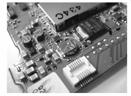
FIG. 1 Soldered rechargeable backup battery in a digital camera
Comatose or Crazy
This situation is trickier. When the unit turns on but is completely bonkers, with random segments on the LCD and improper or no response to control buttons, that usually indicates one of three things: power supply voltages are way off (probably too low), there's lots of noise on the power supply lines or the digital control system is seriously whacked out. Check the supply voltages first. If they look close to what they should be, scope the noise. Using your scope's AC coupling, look at the supply's DC output lines. There shouldn't be more than 100 mv (millivolts) or so of junk on them. If you see much more than that, you can expect to find bad electrolytic caps in the supply.
The most likely culprits are the caps right on the output lines. A good electrolytic will smooth out that noise, so its presence tells you the cap is not doing its job. Even if the part doesn't bulge or exhibit obvious leakage, try replacing it or temporarily putting another cap of the same value across it. Be sure to get the polarity right when you do this! And, of course, shut everything down first and verify that the existing cap is discharged. Don't worry about the two caps adding up to more than the correct value; some extra capacitance on a power supply line will only lead to better filtering. If the noise drops dramatically, change the cap, regardless of whether proper operation was restored when you jumped it with the good one. It might still be bad, but there could be others that will have to be changed before the unit will work again. If the noise drops only a small amount, then the original cap is okay, and you're just seeing the added capacitance smoothing things over a little bit. The trouble is elsewhere.
When you're sure the power supply is working properly, go to the microprocessor.
Check it for clocking, just as with a dead unit. If the clock looks normal, it's possible that the reset circuit, which applies a pulse to the micro's reset pin when power is first applied, isn't working, so the micro isn't starting up from the beginning of its program. Many reset circuits are nothing more than an electrolytic cap between the positive rail and the reset pin, with a resistor going from there to ground. When the cap is discharged and the unit is turned on, the change in the cap's charge state momentarily lets a spike through to the reset pin until the cap charges up and blocks the rail's voltage. If that cap has dried out or leaked, the reset pin won't get tripped, and the micro will start up at some random place in its firmware, resulting in digital insanity. If you can find the reset pin, disconnect power, scope the line going to the pin and then reconnect power. You should see a pulse. If you don't, try turning on the unit. Still no pulse? The reset system isn't working. Try replacing that capacitor. Or, if there's a transistor, diode or other circuit generating the reset pulse, work backward, from its output to its input, scoping your way until you either find a pulse or locate its missing source.
Alive and Awake but Not Quite Kicking
This is where your sleuthing skills really get a workout. The unit powers up and responds properly, but some function doesn't work. Perhaps a backlight is out, or a disc player has trouble reading discs, or a VCR plays only in black and white. Maybe a projector turns on but the lamp won't strike. Figuring out these kinds of failures can take much more work than does troubleshooting the dead and semiconscious types.
After checking for the usual power supply issues, take an especially careful look on the board for bulging or leaky electrolytics. Change any that don't look normal.
Sometimes electrolytics can be bad without showing physical signs. Scope them. As a rule, any electrolytic with one end tied to ground should have very little besides DC on the other end. Especially if you see high-frequency elements to the noise-it's fast or has spiky edges-jump that cap with another one and look at the noise content again.
If these simple checks don't turn up anything, it's time to go snooping. Is the problem at the input side, the signal processing midsection or the output stages? With audio gear, listen for a slight hiss from the speaker. If it's absent, the problem is likely to be in the output stages, because those will produce a little noise even if what's feeding them doesn't work. The speaker itself could be bad too; check with headphones or scope the output lines going to the speaker. With video equipment, there might be some noise on the screen, indicating that the stages driving it are working. With other kinds of devices, it could be harder to tell.
Items that move, like laser heads, print heads and swing-out LCD viewfinders on camcorders, have plenty of problems with broken conductors in their ribbon cables. If a moving part misbehaves, look at its ribbon with a magnifier. Even if you can't see a break, check the integrity of each line on the ribbon using your DMM. The very thin, flexible ribbons with black printed conductors rarely break, but the slightly thicker green ones with copper conductors are quite prone to fractured lines. Even if the conductor side looks black, check the fingers on the ends, where they make contact with the connector's pins. If they're copper-colored or look like they're coated with solder, check the ribbon carefully.
Sometimes Yes, Sometimes No
Want to give a tech nightmares? Sneak up behind the poor sap and whisper the word "intermittent." Watch for neck shivers and twitching muscles. Nothing is more difficult to find than a problem that comes and goes. Naturally, it goes when you look for it and comes back after you're done.
Thermal intermittents represent the easier-to-cure members of the genre. If a product works when cold but quits after warm-up, or the other way around, at least you can control those conditions while you hunt the trouble. Your most powerful weapon is a can of component cooler spray. After the operating status changes state, grab that can and get ready to spray. You don't want to spray the entire unit part by part, so concentrate on the kinds of components most likely to cause thermal problems: those that get warm. Voltage regulators, power transistors, graphics chips and CPUs all generate lots of heat and should show sudden change when you blast them with the spray, if they're the troublemakers. Spray small parts for about a second. Big ones may require as long as 5 seconds. Avoid hitting your skin, as the spray can cause frostbite. And, of course, keep your eyes away! I keep my face at least 12 inches from any part I'm spraying.
Now and then, thermal intermittents occur in small-signal parts too. If a transistor is leaky, it may get warmer than would a properly functioning part, driving itself into thermal weirdness. I remember one radio transceiver (transmitter/receiver) that would peg its signal strength meter to the far right when turned on, and no signals could be heard. As it warmed up, the meter would slowly drop to normal, and signals would gradually rise until they came in loud and clear. Knowing that the meters in radios are driven by the automatic gain control (AGC) circuit, I went hunting in that area. Spray can in hand, I finally found it: a small, garden-variety NPN transistor, leaky as could be. Oddly, it was shorting when cold and started working properly as the current through the short warmed it. Twenty-five cents and three solder joints later, the receiver was back to normal.
Electrolytics can be thermal as well. Of course, a cap shouldn't get hot in the first place. Some get a little warm, especially in switching supplies, but a really hot cap means there's a current path through it, so it's acting like a resistor. In other words, it's leaking.
If you blast any part and the unit starts or stops working, that's a pretty good sign you've found the bad component. When parts are crammed together, you may think you're hitting the right one, but a little bit of the spray is splattering on another component that's actually the culprit. Sometimes you have to spray a few times from different angles to be sure which part you're really affecting, letting the suspect and the components around it warm up again between sprays.
Solder joints can be thermal too. Sometimes when you spray a component and it starts (or stops) working, the real problem is at its joints. Before changing the part, always check the soldering and touch it up if you're not sure. Test again before replacing the component.
Mechanical intermittents are the hardest problems of all to find. When a machine exhibits symptoms by being tapped on, turned or tilted, there goes your night. And the next, and the next, probably.
Vibration or position-sensitive intermittents are caused by bad connections.
They could be cold solder joints, circuit board cracks, dirty connectors, bad layer interconnects or, rarely, fractures inside components. Tap around, see what trips the symptoms, fix it, done. Seems simple enough, right? How hard could this be? Plenty.
These kinds of intermittents tend to be very sensitive, causing malfunction no matter where you tap or flex. The basic search technique is to press and tap ever more gently as you home in on the problem area, hoping to localize the effect until you get down to one spot. Alas, even when you barely touch the board, the part flexing or vibrating may be far from your point of contact.
Circuit board cracks are rare these days, except when a product has been dropped.
Most cracked boards stop working completely, but now and then a cracked trace will have its edges touching just enough to cause a vibration-sensitive intermittent. Far more common are bad layer interconnects, especially the conductive glue variety.
Even plated holes can cause intermittents, but not very often. Conductive glue may look fine but not be making a solid connection with the upper or lower foil traces.
If you suspect a bad interconnect or a cracked trace, jumping with wire, even temporarily, will settle the question. If an interconnect isn't solid with an inner layer of the board, it can be tough to figure out where the jumper should go unless you have a schematic. Because the connection isn't totally lost, though, you can use your DMM to trace to other components. Keep an eye on the actual resistance to avoid reading through other parts and thinking they're connected when they're not. Expect to see some resistance. After all, that's the problem, right? If you see what looks like a connection, tap on the board and see if the reading changes. Remember that a DMM doesn't respond very fast. An analog VOM's needle will bounce, which is more useful in this case.
Many products use the chassis or case as circuit ground, with grounding pads on the board making contact when it's screwed down. As the device ages, loosened screws and oxidation degrade those critical connections, leading to intermittent behavior.
In a unit more than 5 years old, check those pads even if the screws are tight. If the pads are dirty or oxidized, clean them up and see if that cures the symptoms. In a newer item, all should be well unless the screws are loose or the unit has lived in an especially corrosive environment like a boat.
Probably the most frustrating intermittent of them all is when the unit works just fine until you close up the case. Then it either won't work at all or it becomes motion sensitive. You open the case back up again and the little monster works perfectly.
Arggh!
To get to the root of one of these seemingly intractable dilemmas, consider what's happening when the case is closed. Look at the inside of the case and visualize where it will press on the board, on wiring and on ribbon cables. Some cases hold down the corners of the circuit board, flexing it when the screws are tightened. Experiment while the case is open, trying to re-create the problematic conditions. Most of these can be solved, but I've run into a couple I couldn't straighten out.
If the board isn't too sensitive to probe without altering the symptoms, use normal signal tracing techniques to locate the intermittent. If everything you touch disturbs the intermittent, it's very difficult to make sense of what you see on the scope.
To and Fro
Some techs like to work backward most of the time, starting at the output stages and hunting back toward the input area, looking for where the signals stop. Others prefer to start at the input and see where things get lost. What's the best method? Either way may be appropriate. The output-to-input approach is especially useful when there is an output signal but it's not normal. Very often, such problems arise in the output stages and their drivers, so why start way back at the input and scope through stage after stage to get there? If you see a normal signal feeding the output stage, you've pretty much nailed it without a lot of hunting.
Digital devices offer a powerful clue to help you decide your direction of attack: is the time counter moving? If so, the device is receiving data, be it off a disc, a memory card or internal memory, and at least the heart of the digital section is working. So, start at the output and work your way back. If the counter is not progressing, head for the input area and find out why not.
With items like RF receivers, you may have normal audio hiss or video snow but no reception. Since the path through a receiver is fairly complex, with oscillators, tuned IF amplifiers and demodulation stages, it makes more sense to start at the input and work forward. At some point, you'll discover a missing oscillator or a dead IF or demodulator stage, with corresponding loss of signal.
If you are going to work backward, be certain you have a valid input before you start looking for it way down the line! Just because you plug an audio source into a stereo receiver, for example, doesn't mean it's getting to the amplifier board. There could be an issue with the input switching, or your connecting cable might be bad.
Check the input signal at the board to be sure. Camcorder won't play in color? Are you sure the tape you're trying to play has color? If recorded on the same machine, it could be that the fault is in record, not play. Use a known good tape, or verify the existing one by playing it on another machine.
In many cases, a hybrid approach is the most effective. Start at the output and work back a few stages. If you can't find the signal, go to the input and work forward.
In complex systems with multiple inputs, such as servos, check the inputs to be sure they're all there, since one missing signal will turn the whole thing into a mess.
Circuit Stage
Always remember the all-important organizational concept of the circuit stage. You're not going to scope every darned component in the device. Instead, you'll focus on a particular area in the unit and look at it stage by stage.
Test points are very handy. With a schematic, you can look up TP204 and find out what it's supposed to show. Even without a diagram, you can often guess the signal being tapped from the waveform when you scope it. Sometimes you really get lucky, and the test points are labeled for function, in addition to their call numbers. You might see "reset" or "trk gain" (tracking gain). Checking those points and interpreting their signals can save a heck of a lot of work. If a test point at the end of a chain of stages shows the expected behavior, there's no need to scope each stage; they all have to be working.
Test points for digital signals like "reset" may show a line above the word. That means "not reset," which is tech-ese for "the signal goes low to initiate the reset, not high." When there's no line, the signal should go high, but don't count on that.
Some manufacturers don't bother adding the line. If you see one, though, the signal definitely goes low.
Only when you find a nonfunctional stage is it worth trying to discern what part in the stage is preventing it from working. In the vast majority of cases, that part will be either an electrolytic capacitor or an active element: a transistor or a chip.
With a few exceptions, like crystals and high-voltage transformers, other components that may have gone bad are probably victims of having had too much current pulled through them, and are not the perps themselves.
Diodes, rectifiers and zeners represent a special case. Though they're not active in the sense of having gain, they are semiconductors susceptible to the same kinds of failures found in transistors. Most techs think of them as active elements and check them before looking at more reliable components like resistors, coils and ceramic capacitors.
Zeners, which dissipate excess power as heat, are particularly prone to being open. Replacing a marked zener is no big deal because you can look the value up by its part number. Unmarked zeners present a much bigger problem if you don't have the schematic. What was the zener voltage supposed to be? You'll never know for sure, but you can make an educated guess.
First, the zener voltage will be less than what you're measuring at the blown zener, since the whole point of a zener is to reduce the voltage to the diode's breakdown rating; the part does nothing when the voltage is below that value. Theoretically, the zener voltage could be as little as a volt less than the applied voltage, but expect it to be at least a few volts less. Look for electrolytic caps in whatever circuit the zener regulates. The zener voltage will be less than the caps' voltage ratings. Again, it should be at least a couple of volts less, since few designers are foolish enough to run electrolytics all the way up at their ratings.
Though there's a wide range of zener values, many circuits operate on 5, 6, 9 or 12 volts, and it's reasonable to expect most of the zeners you find to be one of those values. Microprocessor circuits commonly use 5 volts. In audio power amplifiers, zeners are used to establish bias, and calculating the correct value isn't simple. Luckily, you should have another channel in which to measure the voltage across its good zener.
Check, Please
When you find a stage that isn't functioning, don't be too quick to indict it. First, be sure it's receiving the power and signals it needs to do its job. You really can't blame the poor transistor if it's not getting voltage, if its bias is way off, or some other stage isn't turning it on or providing proper input.
Unfortunately, cause and effect aren't always so clear. When a signal or a voltage appears to be missing, it could be that the stage is receiving it but a bad part is shorting it to ground. Or, a coupling component could be open, preventing the signal from getting to the active element. How to tell? If there's a resistor between the source of the signal and the stage you're examining, check on the other side of it. The current limiting of the resistor isolates the far side from anything happening at the suspicious stage. The bigger the resistance value, the more isolation you can expect. A few ohms won't give you much isolation-signals will be about the same on both sides-but a kilohm or more sure will. You should be able to see something of the original signal on the other side, even if it's reduced in amplitude.
If not, then the stage on that side isn't sending it, and you need to move your hunt to that part of the circuit.
A capacitor can provide isolation for AC signals, but how much depends not only on the size of the capacitor but also on the frequencies involved. The higher the frequency, the smaller a capacitor it takes to pass it, so the less isolation you get for a given capacitance value.
Once you're certain the correct conditions have been met, it is reasonable to conclude that you have a bad component, and it's time to start checking them. Unless you see a leaking cap, head for the active element first. Even if you find a burned resistor, you can bet the active element pulled too much current through it.
Sometimes parts can be tested while they're in the circuit, but usually the effects of other components will confuse the measurement, and you'll need to pull the suspect part before you check it. Two-legged parts need only one lead disconnected. If one lead goes to ground, remove the other one and leave the ground side connected.
It's easier, since ground lands are typically the biggest and hardest to desolder. Also, you can leave one test lead connected to circuit ground and will have to connect only one lead to the component.
Wick the solder out of the hole and bend the part up on its other lead. For a three-leaded component like a transistor, pull two leads, and be sure one of them is the base or gate lead, so other parts can't influence the sensitive terminal with added capacitance or noise pickup via the rest of the circuitry.
With some parts, especially electrolytics, it might not be possible to bend the component on one lead if the leads are too short. If you can wick the hole thoroughly enough that the stub of the lead moves freely within it, testing is possible without pulling the component. With your test probe, push the stub away from the walls of the hole, watching the test results as you do so. The readings should make it apparent when contact with the rest of the circuit has been broken.
You'll be amazed at how many times you're absolutely sure you've found the problem, you pull the part, and it tests out fine. It can be frustrating, but that's just the nature of the repair experience. Eventually you'll nail it, and it feels really great when you pull the fifth part you were certain had to be the culprit, and it actually is! When All Else Fails: Desperate Measures No matter how good a sleuth you are, sometimes nothing works. You pull part after suspicious part and they're all good. You've been at it for hours, you're out of ideas and desperation sets in. Welcome to the technician's club! It happens to all of us once in awhile. Here are some desperation techniques to try. They may seem crazy, but they're better than giving up and tossing the unit on the junk pile. Now and then, they actually save the day.
Shotgunning
This is as old as electronics itself. When you have an intermittent connection you just can't find, solder them all! Back in the days when circuits had a few dozen parts, shotgunning was easy and quick. Today, with hundreds of joints on every board, shotgunning can take quite awhile, and it's not feasible with laptops and other extremely dense, complex products.
Start with an area you think is causing the trouble and hit every joint in it. If it doesn't work, keep on going. Don't be surprised if you wind up redoing every joint in the entire product, and it still won't work. Frankly, shotgunning is rarely successful; the real problem always seems to be something obscure that gets missed. Now and then, though, luck prevails and the symptoms disappear. Don't get too excited-you might have only wiggled the actual bad connection, and the problem will return… typically right after you tighten the final case screw. Once in a great while, I've seen shotgunning result in a real repair.
Current Blasting
This one has a little more basis in sanity. It's useful only when you have a dead short across the power supply rails somewhere on the board, but you can't find it.
Especially on today's digital boards, there are lots of little bypass capacitors from Vcc (the positive supply rail) to ground. Now and then one of them shorts. You see the short no matter where on the rail you probe with your ohmmeter, so it's impossible to deduce which of the 50 little caps might have become a zero-ohm nightmare, and pulling them all to test them presents too much risk to the board. Plus, it'd take hours, and you can't be sure the short isn't in some other component anyway.
There exist exotic ohmmeters that read ultra-low resistance values down in the milliohms (thousandths of an ohm), allowing you to follow the traces and see when you're approaching the short. You don't have one of these babies, though, and neither do I. Even if you did, it would be hard to check the whole board and make sense of what you see.
There's a faster, easier way. You probably have a high-current power supply, either on your bench or perhaps in a discarded desktop computer. To perform current blasting, you need a supply of the same voltage as the product's supply. Many of these direct-short situations involve 5-volt digital boards, so a computer supply is a good choice. You need a lot of current-perhaps 20 amps or so. Your little 2-amp variable bench supply won't do it, but a PC supply has the required oomph.
If at all possible, disconnect the product's own power supply so you won't be feeding voltage into its output. That's usually okay, but some voltage regulators can be damaged when their output voltage exceeds their input voltage (which will be zero in this case), so it's best to avoid having them connected during this maneuver. If there's a removable fuse between the supply's output and the rest of the board, pulling that should do it. Otherwise, yank the connector or unsolder the positive wire.
With the hefty supply turned off, connect its +5V and ground wires to the board's supply rail and ground traces. Naturally, + goes to +. Make sure you're past any fuses, because this procedure will blow them. This is one time you don't want protection. Turn on the supply and wait. After perhaps 30 seconds, the shorted part will start smoking and burning, because pretty much all the supply current is going through it. As soon as you see the smoke, kill the supply; you've found the bad component. If the part is something nonessential, like a bypass cap, the product may start working as the current cooks the cap. I've seen the voltage rise high enough to start up a device even before the short clears. It's amazing what enough current will do.
This procedure will work with other voltages too, of course, as long as you have a supply that can source a lot of current.
Some caveats: it's possible the board's traces could melt before the shorted part gets hot enough to smoke. I haven't seen that happen, but it could. On a dense or multilayer board, a melted trace could prove disastrous. Also, the big supply must not have self-protection or it'll refuse to dump lots of current into a short. I've had good luck with desktop PC supplies; they are very sturdy and don't mind the overcurrent, at least not for the period of time required. They also don't seem to have self protection circuitry.
If nothing gets damaged, current blasting pretty much always works when the shorted part is a capacitor. Sometimes the short is inside a chip, and the high current instantly blows it open. Nothing smokes, you don't know where the short was, the device still doesn't work, and you're no better off than when you started. Still, it's a useful technique and it beats just giving up.
I once fixed a really nice little hard-drive MP3 player that way. It had a dead short across the power supply input jack, and the board was too small and dense for me to consider trying to pull parts and test them. It was a 5-volt unit, so I hooked up a computer supply and hit the switch. In 10 seconds a surface-mount electrolytic cap right next to the power jack lit up like a tiny light bulb. I changed it and the unit came back to life. I saved a rather expensive digital piano with current blasting too. The shorted component was a tiny bypass cap near the microprocessor. I'd never have found it any other way.
LAP (least accessible place ) Method
This is the craziest last-ditch method of them all, but it has worked for me on rare occasion. LAP stands for "least accessible place." Where's the hardest place to reach in the entire product? If every other option has been exhausted, head there and suffer through whatever it takes to examine that difficult area. After a few LAP successes, I used to wonder how this could possibly be real. Was some cosmic force hiding things from me? Was there a ghost in the machine with a bad sense of humor? The more reasonable explanation was that it was the one place I hadn't been yet! It seems like no matter how hard we try to check everything, there's always some forgotten nook so inaccessible that we don't even notice it, or we subconsciously avoid it. And, if it's the last possible place, the trouble just might be there.