Another useful application of flip-flops involves connecting several of them together to form a shift register. Shift registers are available as self-contained circuits on a single chip. It’s important to understand the circumstances that require the use of a shift register before one can fully understand its operation. A simple example is shown in Fig. 11. This application is a painting line for small wooden toys. The toys are moved on a continuous line past the painting nozzles. The spacing of each toy on the line is maintained by an auger system. When the toys move into the painting booth, they pass four painting nozzles. The first nozzle sprays a sealer coat, the second sprays a primer coat, the third sprays a color coat, and the fourth sprays a clear coat as a finish. The line moves the wooden toys continuously past each nozzle and the nozzles are timed so that they are energized to spray paint on each toy as it passes directly in front of a particular nozzle. Since the line runs continuously, the number of toys painted each hour is considerably higher than if the line was jogged and stopped each time a toy was in front of a nozzle. The only problem that arises with this process is when a toy is not present on the line. If a toy has fallen off the line prior to entering the spray booth, or if there is a gap in the line of toys, the sprayer nozzle would waste paint trying to paint the space where the toy should have been.
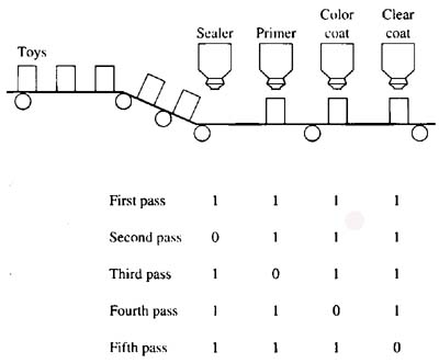
Above: Fig. 11: A shift register is used to control four painting nozzles in a toy-painting application. The toys move past the nozzles on a continuous line, and if a toy is missing, the shift register de-energizes each nozzle as the blank space moves past it. If a toy is present on the line, the shift register energizes each nozzle as the toy moves in front of it. A table is provided at the bottom of the figure to show the bit pattern in the shift register to indicate when a toy is missing from the production line (1 indicates toy is present; 0 indicates toy is missing).
The shift register is used to keep track of whether a toy is present or absent in each space on the line. A sensor is mounted at the point where the toys begin to enter the spraying area. The information from the sensor is stored as a 1 if a part is present and as a 0 if a part is missing, and it’s passed to each spray nozzle as the line moves. If a toy is present, a 1 is passed to the solenoid that energizes the nozzle, and if a toy is not present on the line, a 0 is passed to the nozzle solenoid, which will ensure that the nozzle remains de-energized. Since an auger maintains exact spacing as the toys enter the spray booth, it can also be used to provide the clock pulse for the shift register. A photoelectric switch is used as the sensor to determine if a toy is present or absent on the line.
If a condition occurs where the parts must be cleared off the production line in the painting booth, the shift register must be reset. In the reset condition, 0’s are placed in each output to ensure all of the spray-painting heads are turned off. The reset condition is accomplished by sending a signal to the reset line of the shift register.
Operation of a Shift Register
The shift register must have a clock input and a data input to operate correctly. The number of shift locations will depend on the application. In the spray-painting example, there are four nozzles so the shift register has four bit-shift locations. Each bit of the bit shift register energizes one output. The data input is the photoelectric switch that senses whether or not a toy is present on the line. Since the auger that provides the spacing for the toys on the line is chain driven by a sprocket and gear, a proximity switch can sense the tip of each tooth of the gear and determine the amount of movement of the toys on the line. The signal from the proximity switch is used as the clock input for the shift register. It’s important for the clock input to be referenced to the spacing of the toys so that the data bits are shifted to the output solenoids to energize them at just the right time when the toy is in front of the spray-painting nozzle.
The example starts with the line running and a toy is present in each position. The table in the bottom of Fig. 11 shows the bit pattern in the shift register as the toys pass to be painted. A 0 is used to represent the space where a toy is missing and tracked through the system and a 1 is used to show a toy is present. The first line of the table indicates a toy is present in front of each nozzle. Notice the bit pattern is 1111. Each output that has a 1 activates the spray nozzle connected to it.
The second line in the table shows the bit pattern when the second clock pulse occurs. Since a toy is missing at the entrance of the paint booth when the second clock pulse occurs, the sensor that is connected to the data input senses this and places a 0 in the first position of the shift register. The clock pulse is provided when the auger moves the toys one position. Since a toy is missing in the first position, the bit pattern in the shift register is 0111, so the nozzle for the sealer is dc-energized and no sealer is sprayed. Since the other three positions have toys present, the shift register has 1’s representing their positions and those nozzles are energized.
In the next step of the cycle, notice that the line is moved once more, which moves the empty space in front of the second nozzle. and the 0 that represents the missing toy is shifted to the primer nozzle. The bit pattern for this step is 0100. That is, the primer nozzle is dc-energized while the other three nozzles are spraying. Also notice that since the space directly behind the missing toy is now filled with a toy, the shift register will place a 1 in this position to energize the sealer nozzle. The 0 that represents the missing toy will continue to be shifted one space to the right each time the toys are moved by the auger. This ensures that the 0 in the shift register will follow the empty space on the line. This is shown in the table as you follow the remaining clock pulses.
Using Edge-triggered JK Flip-Flops to Make a Shift Register
Fig. 12 shows a shift register circuit made from edge-triggered JK flip-flops. This circuit shows four flip-flops that all have their clocks tied to a common line, which is connected to the sensor in the system that will act as the clock. For instance, in the painting circuit this line is connected to the sensor that detects the movement of the auger to ensure exact spacing of the toys on the line. The output for each flip-flop is connected at each Q terminal. The data in line is connected to the sensor that detects whether or not a toy is present. This line is also connected to the J input of the first flip-flop. An inverter also sends an inverted copy of the data (1 or 0) value to the K input of the first flip-flop. Each time the clock is transitioned, the contents (1 or 0) of the first flip-flop are sent to the second flip-flop, and the contents (1 or 0) of the second flip-flop are sent to the third, and so on. If the first flip-flop is storing a 1, its Q output will send a 1 to the next flip-flop and to the first output. Since each output device, such as the solenoid for the painting nozzle is connected to the Q output of each flip-flop, the output device will be energized when the flip-flop output is a 1, and it will be dc-energized when the flip-flop output is a 0.
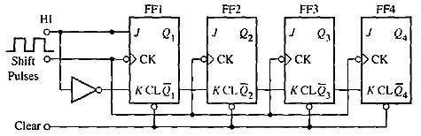
Above: Fig. 12: Four positive edge-triggered JK flip-flops connected together to provide a shift register. The clocks of each flip-flop are connected together and the Q output of each flip-flop is connected to the J in put of the next. The value (1 or 0) that is stored in each flip-flop is shifted from its output to the in put of the next flip-flop each time the clock is pulsed.
A number of different types of shift registers are available to provide bit shift functions for a variety of applications. Fig 13 shows some of the different types of bit shift registers.
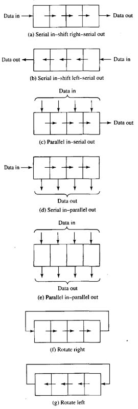
Above: Fig. 13: (a) Shift register that shifts bits from left to right in a serial format. (b) Shift register that shifts bits from right to left in serial format. (C) Shift register that provides parallel (word) data in and serial data out. (d) Shift register that provides serial data in and parallel (word) data out. (e) Shift register that provides parallel (word) data in and parallel (word) data out. (f) Shift register that rotates one bit to the right. Notice the output of the shift register is tied back to the input. (g) Shift register that rotates one bit to the left. Notice the output of the shift register is tied back to the input.
Using Shift Registers to Provide Time Delay
Shift registers are also used in industrial circuits to provide accurate time delay at the microsecond or nanosecond time base. One example of this application is in high-speed aluminum can manufacturing. When aluminum beverage cans are manufactured, they are also inked with the product logo. This process occurs on a continuous line as the cans are made. If the can does not receive the proper amount of ink at the proper location, the can won’t be acceptable. A detection system is used to determine if a can is properly inked as it leaves the printing machines. Since the cans move through the production equipment at very high speeds (up to 1500 cans a minute), it becomes difficult to remove the bad can after it has been detected. A blow-off system uses high-pressure air to blow the bad can off the line as it passes by. The problem arises in timing the blow-off apparatus so that it removes only the bad can. The blow-off system requires several milliseconds to energize a solenoid valve and get enough air pressure to the nozzle to remove the can.
The shift register is used to provide an accurate amount of time delay to align the position of the bad can with the nozzle at the exact time when the air comes out of the nozzle. This shift register is slightly different from the one used in the spray-painting application in that it only needs one output, which is provided by the Q output of the last flip-flop. Since a bit is advanced through one flip-flop each time the clock is transitioned, the number of flip-flops in the shift register will represent the amount of time delay that occurs for the bit to be moved from the input of the first flip-flop to the output of the last flip-flop. By adding or subtracting flip-flops (bit positions) in the shift register, the amount of time delay can be accurately adjusted.
Word Shift Registers
In some applications it’s important to shift an 8-bit word or 16-bit word that represents a number rather than a single bit that indicates something should be turned on or off. An example of this type of logic circuit is shown in Fig. 14 where a painting system becomes more complex. In this application a set of complex painting robots is used to apply primer, base coats, and clear coats to automobiles on an assembly line. The simple shift register is used to indicate when an automobile is present or not, but a more complex word shift register is used to pass the number that represents the paint color to each robot. Some base colors may require a red colored primer coat, while lighter colors require a gray primer coat. The robot that provides the base color can change colors for each automobile as it passes if necessary. New painting technology provides several means to ensure that the nozzle is clean as it begins to spray a new color. The robot must be told which color to apply so that it can energize the proper solenoid.
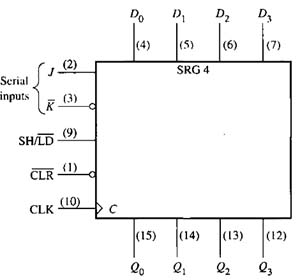
Above: Fig. 14: Word shift register used to transfer values representing paint colors from station to station in a robotic painting line. The numbers are used to indicate the proper paint color a robot should use on the automobile body as it passes on the assembly line.
In this application, the color of paint for each automobile is specified when the car is ordered. The number that represents the paint color will accompany the body of the car as it’s assembled and moved through the plant. When the car reaches the painting robots, the number for its paint color is entered into the data input line of the shift register, and it’s passed to each stage of the painting system so that each robot sprays the correct color of paint.
Each stage of the word shift register has the number of bits to represent the number. Recall that in digital electronics that you can represent values 0-15 with four bits, and values 0-65565 with sixteen bits. The word shift register can use any number of the 0-15 bits provided to represent the values for the paint numbers.

