Counters are widely used in industrial electronic circuits. The counters are used as up counters, down counters, totalizing counters, reset counters, decade counters, encoders, and decoders. The first part of this section will discuss the chips that are used to provide these functions, and the last part of this section will discuss solid- state devices that are specifically designed for these purposes.
Up counters, down counters, and totalizing counters are used for simple functions such as counting the number of parts a machine has made. These counters can also be used as reset counters that provide an output when the counter reaches a predetermined count. For instance, a palletizing machine may need to count the number of boxes as it fills layers on a pallet. Since each layer needs four boxes, the counter is set to 4. When the fourth box is counted, an output is sent from the counter. The output is used to index the machine to the next layer. This feature of the counter is called reset, since an output is energized when the stored value (count) reaches the preset value and the stored value is reset to zero.
In their simplest forms the counters maybe used for a variety of logic functions: binary counters, flip-flop counters, binary coded decimal counters, decade counters, and cascaded counters. The examples in this text will begin with asynchronous and synchronous counters.
Asynchronous and Synchronous Counters
Counters can be classified as asynchronous or synchronous based on the type of clock pulse the counters use. The flip-flops in an asynchronous counter don’t all change state at the same time, whereas all of the flip-flops in the synchronous counter are clocked simultaneously. The asynchronous counter is also called a ripple counter, since the signal sent to the input of the first flip-flop is sent through the remaining flip-flops like a wave that ripples outward when a stone is thrown into a pond. The most common types of asynchronous counters are the four-bit binary counter and the decade counter.
The four-bit binary counter uses four edge-triggered flip- flops to count values from 0-15 in a binary format. Fig. 8a shows the four positive edge-triggered JK flip-flops connected together so that output Q0 is connected to the clock of FF1. The output of Q1 is connected to the clock of FF2, and output Q2 is connected to the clock of FF3. Output Q3 represents the most significant bit (MSB) of the counter, and output Q0 represents the least significant bit (LSB) of the counter. The table in Fig. 8b shows the binary bit pattern and the equivalent decimal value that would be read at the four outputs for each clock pulse of the counter. All of the JK inputs are tied HI so that the flip-flops will pulse with each signal sent to the clock input from the previous output. The counter can be reset (cleared) at any time by signals sent to the CLR terminal of each flip-flop.
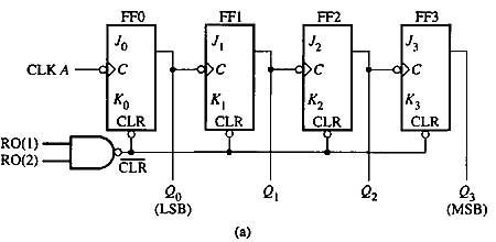
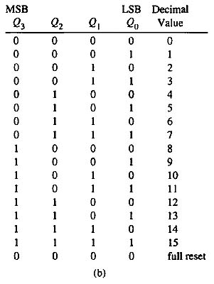
Above: Fig. 8(a) Four flip-flops connected as an asynchronous counter. The output lines can count values 0-15 in bi nary format. (b) The binary bit pattern and equivalent decimal value for the asynchronous Counter.
The four-bit synchronous counter is shown in Fig. 9. From this diagram, notice that all four of the flip-flops have their clocks connected to the same line, which is pulsed (strobed) when the counter is incremented. The counter still has the ability to count values from 0-15. The terminals of the counter are identified as Q0, Q1, Q2, Q3 clock, and clear. Notice that the counter is reset after the value 15 is counted.
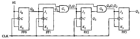
Above: Fig. 9: Four-bit synchronous binary counter. Four flip-flops are used to make this counter. All of the flip-flops change state with the common clock pulse.
Binary Coded Decimal Counters
The binary coded decimal (BCD) numbering system uses a combination of four binary bits to represent decimal values 0-9. Recalling basic digital concepts, realize that the four binary bits can represent values 0-15, but since the decimal numbering system only uses values 0-9, the remaining values (10-15) don’t need to be represented. Fig. 10a shows an example of the number 467 represented as a BCD number. From this figure notice that the four bits that represent the hundreds column display the binary value of 0100, which is the decimal value 4. The second set of four binary bits is used to display values in the tens column, and it shows the binary value of 0110, which is the decimal value 6. The third set of four binary bits is used to display values in the ones column and it shows the binary value of 0111, which is the decimal value 7.
The BCD numbering system is used with many electronic devices such as thumbwheels that are based on the decimal numbering system (0-9). In the BCD counter the flip-flops for each set of four binary bits are used to count only values 0-9, and then the set of four flip-flops is reset to zero. A second set of four flip-flops is used for the digit (0-9) that represents the ten’s column for the decimal number. A third set of four flip-flops is used to represent the digits (0-9) in the hundreds column of the decimal system. Since this type of counter counts ten values (0-9), it’s also called a decade counter.
It’s important to remember that the main feature of the BCD counter is that it changes to the reset value (0000) after it reaches the value for 9 (1001) rather than move to the binary value for 10 (1010). Each additional set of flip-flops in the BCD decade counter counts values that are ten times the value of the previous set. This provides the function of decimal weighted values such as one’s, ten’s, and hundred’s columns for each set of flip-flops.
Figure 10b shows an example of a counter that uses three BCD counters to count decimal values 0-999. This type of counter combines three individual BCD counters so that one counter counts values for the decimal one’s column, a second counter counts values for the decimal ten’s column, and a third counter counts values for the decimal hundred’s column. This type of counter is called a three- digit BCD counter.
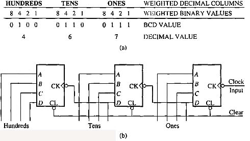
Above: Fig. 10(a) An example of the BCD numbering system displaying the value of 467. (b) Three individual BCD counters are combined to make a three-digit BCD counter. The three- digit BCD counter can count decimal values from 000 to 999.
Up/Down Counters
Up/down counters are frequently used in industrial applications where values can be added or subtracted from one register. The up/down counter consists of a load register, a clock line, a reset line, and a max/mm output line. The register is incremented (1 is added to its total) or decremented (1 is subtracted from its total) each time the clock line to the counter is transitioned. The initial value can be preset in the register using the four load lines. The counter then counts up or down until it reaches the maximum or the minimum value for the register. The max/mm output of the counter goes true when the value in the register reaches either of these conditions. Some counters provide a second output for the full condition. The counter can be cleared by simply loading all 0’s from the load inputs. The up! down input determines the direction the counter counts.
The up/down counter is generally used to keep track of good and bad parts in a production line. Each time a machine makes a part, the up-count input line is transitioned so that the count is incremented. After the parts are inspected, they are sorted and classified as good parts or bad parts. Each time a bad part is detected, the down-count input line is transitioned and the counter will decrement the total. At the end of the shift, the value in the counter register will be the total number of good parts. Another way of thinking about the value in the counter register is to think of it as the total number of parts that were made minus the number of bad parts. If the total number of parts manufactured and the total number of bad parts need to be counted separately, two additional up counters can be used to count these specific parts. It’s also possible to cascade one counter to another if larger values are required to be counted.

