In more advanced solid-state logic applications, the state of a logic bit may need to be stored. This can be accomplished by using a latch. A latch is a bistable storage device that can reside in either the set or reset state by virtue of feedback from its outputs. Since the latch has two stable states (HI and LO), it’s called bistable and its output indicates whether a 1 or 0 is stored. Fig. 1 shows an RS latch, and its equivalent NAND gate logic and truth table.
RS Latch
The operation of the RS latch shown in Fig. 1a can best be explained by the example with two NAND gates shown in Fig. 1b and the truth table shown in Fig. 1c. The inputs of the latches are identified as S for set and R for reset, and the outputs are identified as Q and Q (Q NOT). This latch may also be called the SR latch.
When a HI input is applied to the S input and the R input is held LO, the Q output will be high, and the Q will be low. In this state the latch is storing the status or condition of the HI signal that is sent to the S input. In most cases this signal is toggled, which means it may only stay HI for an instant. After the input signal goes LU, the latch maintains the HI condition at the Q output. This is called the latched condition.
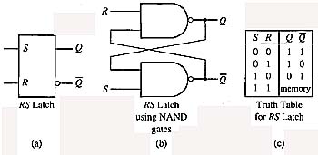
Above: Fig. 1 (a) RS latch. (b) NAND gate logic for RS latch (c) Truth
Table for RS latch.
The latch can be reset when a HI signal is sent to the R input. The S input must be LO at this time for the reset function to be accomplished. When the latch is in the reset state, the Q output will be LO and the Q output will be HI. If a LO signal is sent to both the S and R inputs, the outputs of the latch become unpredictable and this state is called invalid. The RS latch is used in many memory applications. Since it has the ability to latch, it’s also used as a bounce eliminator or in circuits where electromechanical switches are used as inputs to logic circuits. If the contacts bounce when the switch is closed, the logic device will only see the first contact closure.
Another application of the RS latch is a control circuit used in sonic-welding or spot-welding systems where multiple welders are used and the amount of current is limited so that only one of the systems may be operated at a time. For instance, if the system has two welding heads, a set of latches can ensure that if both systems are energized at the same time, the first one that transitions to the on-state will set its latch and lock out the other’s latch. When the first welder’s cycle is complete,
it will enable the latch of the second so its weld can proceed. Since each weld lasts for only 2-3 seconds, the latch circuit can control the systems so that only one fires at a time and allows the second to energize as soon as the first has completed its cycle.
Edge-Triggered Flip-Flops
The edge-triggered flip-flop is a synchronous bistable device that only changes state when a specific point on a clock signal occurs. The edge-triggered flip-flop is called synchronous because the data available on its inputs are transferred to its outputs when the edge of the triggering clock pulse is present. This makes the edge-triggered flip-flop different from the latch in that it only changes state when the proper clock pulse is received at its clock input, and the latch can change state any time the correct sequence of input signals transitions. Edge-triggered flip-flops include the R-S flip-flop, the D-type flip-flop and the JK-type flip-flop. The R-S flip-flop is also called the S-R flip-flop.
The edge-triggered flip-flop is available as a positive edge-triggered or a negative edge-triggered device. A positive edge-triggered flip-flop is pulsed by the leading edge of the clock pulse called the positive edge, and a negative edge-triggered flip- flop is pulsed by the trailing edge of the clocked pulse called the negative edge. The positive edge-triggered flip-flop will read its inputs when the clock pulse transitions from LO to HI, and the negative edge-triggered flip-flop will read its inputs when the clock pulse transitions from HI to LO.
Fig. 2a shows a positive edge-triggered RS flip-flop, the positive edge- triggered D flip-flop, and the positive edge-triggered JK flip-flop. Fig. 2b shows a negative edge-triggered RS flip-flop, the negative edge-triggered D flip-flop, and the negative edge-triggered JK flip-flop. In these diagrams one should notice the small triangle at the clock input that indicates this is an edge-triggered device. A small circle will be placed in front of the triangle for all of the flip-flops in Fig. 2b to indicate the flip-flop is negative edge-triggered.
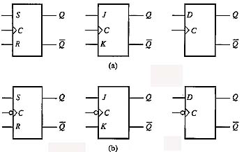
Above: Fig. 2 (a) Symbols for the positive edge-triggered RS flip-flop, the positive edge-triggered JK flip-flop, and the positive edge-triggered D flip-flop. (b) Symbols for the negative edge-triggered RS flip-flop, the negative edge-triggered JK flip-flop, and the negative edge-triggered D flip-flop.
The Edge-Triggered RS Flip-Flop
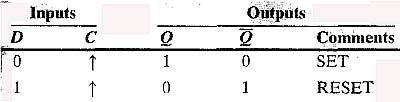
Fig. 3 shows the truth table for the positive edge-triggered RS flip-flop. Here one may notice that the positive edge-triggered flip-flop won’t change the output state when both R and S inputs are LO when the clock pulse occurs. If the S input is LO and the R input is HI when the clock pulse occurs, the output will be LO. If the S input is HI and the R input is LO when the clock pulse occurs, the output will be HI. If both the S and R inputs are HI when the clock pulse occurs, the output state is invalid.
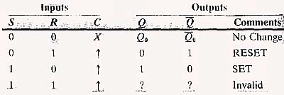
Above: Fig. 3: The truth table for the edge-triggered RS flip-flop.
The Edge-Triggered JK Flip-Flop
Perhaps the most widely used flip-flop, the JK flip-flop is similar to the RS flip-flop but has no invalid states. That is, all conditions of the outputs can be predicted for every set of inputs. The letters J and K don’t represent any condition such as the R and S for reset and set. Fig. 4 shows the truth table for a positive edge-triggered JK flip-flop where one may notice that the flip-flop has no invalid states and its conditions are similar to the RS flip-flop. If the J and K inputs are both LO when the positive clock pulse is received, the Q output won’t change state. If the J input is LO and the K input is HI when the positive clock pulse is received, the Q output will be LO and the Q will be HI. If the J input is HI and the K input is LO when the clock pulse is received, the Q output will be HI and the Q output will be LU. If the J and K inputs are both HI when the clock pulse is received, the output will toggle, which means that if the Q output is HI it will go LO and if it’s LO it will go HI.
From the diagram in Fig. 4 one should notice that the output conditions are described as the reset, set, and toggle modes. The reset and set conditions are exactly like the RS edge-triggered flip-flop, except when both inputs are HI the output will toggle when a clock signal is received. For instance, if both the J and K inputs are HI and the Q output is HI, it will transition to the LO state when the clock pulse occurs. If the two inputs remain high, the Q output will transition from the LO state to the HI state when the next clock pulse occurs. This type of flip-flop circuit is useful in applications where the output must be alternately HI and then LO when both inputs are HI.
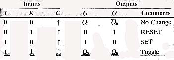
Above: Fig. 4 : The truth table for the positive edge-triggered JK flip-flop.
The Edge-Triggered D Flip-Flop
The edge-triggered D flip-flop stores the single data bit that is present at the D input on its Q output when the clock pulse is received. In other words, if a HI signal is present at the D input when the clock pulse occurs, the flip-flop will set and the Q output will become HI. If a LO signal is present at the D input when the clock pulse arrives, the flip-flop resets and the Q output will become LO. The output will remain in its present state until a clock pulse occurs. Fig. 5 shows the truth table for the positive edge-triggered D flip-flop.
Above: Fig. 5 The truth table for the positive edge-triggered D flip-flop.
Using Flip-Flops to Cycle Two Air Compressors
Fig. 6 shows an example of using flip-flops for industrial control circuits. This circuit shows a positive edge-triggered JK flip-flop used to cycle two air compressors. In many industrial applications air supply systems use two small air compressors instead of one large one. This allows one to be the backup if a failure occurs. Since air is used to operate tools, move robots, and open and close clamps and fixtures with air cylinders, it’s important that the air source is not interrupted. Since two compressors are used, it’s also important that one does not work harder than the other. A flip-flop can be used in the control circuit of the two compressors to ensure that each compressor runs approximately the same amount of time.
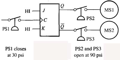
Above: Fig. 6: A clocked JK flip-flop used to control two air compressors to ensure they run approximately the same amount of time.
When the pressure in the air tank drops below 30 psi, pressure switch PSI closes and sends a signal to the clock input of the flip-flop. Since both the J and K inputs are held HI, the flip-flop will toggle the Q and the Q outputs. The coil (MS1) for the motor starter that controls air compressor 1 is connected to the Q output and the coil (MS2) for the motor starter that controls air compressor 2 is connected to the Q output. During the first cycle, the Q output will be HI and the coil of motor starter 1 (MS 1) will be energized. When the compressor builds up the pressure to 60 psi, pressure switch PSI will open. When the air pressure drops below 30 psi, pressure switch PSI will close and provide another clock pulse. This time when the clock pulse occurs, the outputs will toggle and the Q output will be LO and the Q output will be HI, which will energize the motor starter coil (MS2) for the second air compressor. Each time pressure switch PSI opens and closes, the outputs of the flip-flop will toggle. This will cause both air compressors to run approximately the same amount of time so that neither of them has to do all of the work. Pressure switches PS2 and PS3 are safety switches that will turn off the air compressors if the air in the system exceeds 90 psi, which is an unsafe condition.
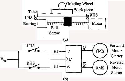
Above: Fig. 7: (a) A diagram of the surface grinder that shows the location of the left-hand switch (LHS) and right-hand switch (RHS). (b) Example of a clocked JK flip-flop used to control the back-and-forth action of the table of a surface grinder.
Using Flip-Flops to Control an Industrial Surface Grinder
Another application using the edge-triggered JK flip-flop is in a circuit to control the operation of a surface grinder. Fig. 7 shows a diagram of the surface grinder and the circuit that makes it operate. The surface grinder is used to move a piece of metal back and forth under a grinding wheel to remove small amounts of surface or to polish the surface. The piece of metal that is to be finished is clamped in a fixture that is mounted to a movable bed. If one is standing in front of the grinder table, the back-and-forth movement of the table will look like the table is moving from left to right, and when it reverses, the table will move from right to left. A motor is used to provide this movement as it rotates in the forward and then in the reverse direction.
A second motor is used to control the table’s index motion. The index motion moves (indexes) the table at the end of each pass. The indexing action is similar to mowing your lawn. If one kept the same path each time one went back and forth across the yard, one would only mow one small swath across the yard. By moving the mower to the next row of grass each time, one ensures that he/she will cover the entire surface of the lawn.
When the surface of a flat piece of metal 3 inches wide and 15 inches long is polished, the table must move back and forth at least 20 inches so that the entire piece is covered. The amount of distance the table must be indexed at the end of each stroke is determined by the thickness of the grinder wheel. If a 1-inch wheel is used, the grinder table will be indexed approximately 3/4 inch each time to ensure a small amount of overlap occurs. This guarantees the entire surface is machined. The depth of cut can also be controlled by moving the table up and down or by moving the grinding wheel up and down so the grinding wheel cuts deeper into the surface. The depth of cut is usually adjusted after the grinding wheel passes over the entire surface.
For the first part of our example, we will discuss the flip-flop controlling only the back-and-forth motion of the table. A similar circuit would be used for each of the other two axes of motion.
In this diagram, notice the grinder has a limit switch mounted at each end to detect the travel of the table. The limit switches are connected in parallel (OR logic) to the clock input of the flip-flop. The J and K inputs are connected to a HI signal so that the flip-flop will stay in the toggle mode. Also notice that the forward motor starter (FMS) is connected to the Q output, and the reverse motor starter (RMS) is connected to the Q output. ( If you need more information Google “reversing motors”.)
When the grinding cycle is started, the FMS is energized and the motor will turn clockwise, which moves the table from left to right. When the table moves the full amount of distance to the right, it will strike the right-hand limit switch (RHLS). When the table strikes the limit switch, the switch will transition from open to closed, which will provide the leading edge pulse for the clock signal.
When the flip-flop receives the clock pulse, it toggles and the Q output is energized and the Q (Q NOT) output is de-energized. The Q (Q NOT) output energizes the RMS, which makes the motor shaft turn in reverse rotation and causes the table to move back the other direction to the left. As the table moves to the left, it moves away from the RHLS, which allows it to transition to its open position again so that it’s ready for the next cycle.
The table moves in the reverse direction (left) until it strikes the left-hand limit switch (LHLS). When the table moves against the LHLS, its contacts transition from open to closed. Since it’s also connected to the clock input of the flip-flop, the flip-flop will toggle, which will cause the Q output to become energized and the Q (Q NOT) output to be de-energized again. When the FMS is energized, it causes the table to move back to the right again. As the table moves to the right, it moves off of the LHLS, which allows it to transition to its open position making it ready for the next cycle.
Each time the table makes the travel in both directions, a pulse is provided to a timer that controls the amount of time the index motor for the table is energized. The index motor is usually energized for less than 0.1 second to provide approximately 3/4-inch travel. When the index moves the full amount of travel, it will strike a limit switch, which will provide the clock pulse to its flip-flop and the table index motion is reversed. When the part is indexed in both directions under the grinding wheel, a pulse is sent to a timer that controls the depth-of-cut motion. On this machine the depth of cut controls the travel of the grinding wheel down into the surface. When the depth-of-cut limit switch is activated, the machine turns off to indicate the end of the cycle.
Using Flip-Flops for Safety Circuits
Edge-triggered JK flip-flops are also useful in safety circuits where the safety switches or devices may be jumpered out. In many older industrial control circuits, it was a common practice to place jumper wires around guard safety switches, door switches, palm buttons, and other safety devices to get around their use. This practice created many accidents where operators or technicians were injured. In newer circuits, the edge-triggered JK flip-flop is used to ensure the safety device is toggled once each cycle. If the safety device must toggle once during each cycle, it’s impossible for the machine to operate if the safety device has been jumpered out.
Flip-flops can also be used on anti-tie-down circuits that require the operator to have both hands on palm buttons to start a cycle. These types of safety circuits are specified on presses or other systems where operators may be able to get their hands near the moving parts of a machine when it’s started. By requiring operators to have both hands on the palm buttons, it ensures that their hands are in a safe place. The flip-flop is used in toggle mode to ensure that one or both palm buttons are not tied down or jumpered out.
Flip-flops are also used in newer gas-heating systems where exhaust gases are removed with a blower motor. The system won’t allow ignition to take place unless the exhaust blower is running and creating the correct amount of pressure drop across a pressure switch. One side of the switch is connected to check the draft (negative pressure from the blower) and the other side of the switch is used to detect the pressure side of the blower. If this switch is jumpered out after ignition is established, the heating system will continue the cycle it’s on, but the flip-flop will disable the ignition circuit if the switch does not change positions when the blower stops at the end of the cycle. The flip-flop ensures that the pressure switch sees the higher pressure created by the blower motor at the start of the circuit and then sees the low pressure, which indicates the blower motor has shut off at the end of its cycle. If the switch has been jumpered out, it won’t toggle the flip-flop and ignition won’t occur. The pressure switch is used in the furnace to detect a faulty exhaust motor, and the flip-flop is designed to prevent anyone from tampering with the pressure switch.

