Another example of using logic to store data and retrieve it’s called a first-in, first- out register (FIFO). FIFO is used to store fault codes. In many complex automated industrial systems, sensors are used to detect a number of faults such as loss of voltage, excessive current, low current, loss of air pressure, loss of motion, and over-temperature. Any one of these conditions may occur and cause the machine to shut down, which will cause other conditions to be sensed. For instance, if the sensors detected an over-temperature condition, the system would be shut down and the loss of motion, low current, and loss of voltage sensors may also be affected. When the technician arrives to troubleshoot the system, multiple fault lights would be illuminated, which may make detecting the problem confusing. Fig. 15 shows examples of FIFO used in a fault detection system, and Fig. 16 shows a diagram of a typical 16-bit FIFO chip. Advancements in technology have provided FIFO chips that have typical stack sizes of 1024 words.
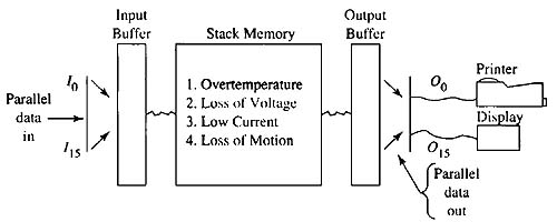
Above: Fig. 15: Example of the first-in, first-out register being used as a fault detection system. Each fault has a fault code number that is placed in the FIFO register in the order that the fault occurs. The printer and display are used to show the order that the faults occurred. This ex ample shows the fault as the name rather than the number that represents the code.
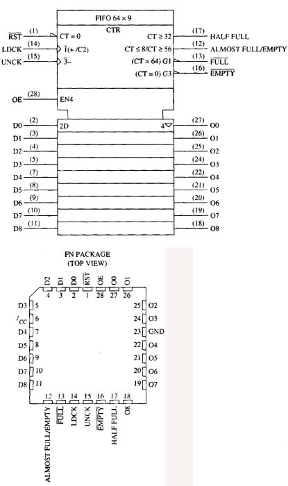
Above: Fig. 16: Diagram and pin outline of typical FIFO chip.
A FIFO register could help this problem by assigning each fault condition a number and storing the fault numbers in a stack (register) as they occur. If the over-temperature condition occurred first, its fault code would be placed in the register first. When the machine begins to shut down in response to the over-temperature and switches are opened and a solenoid de-energizes and shuts off the air, each of these conditions will be recorded in its order of occurrence by placing the fault code in the register and moving the previous code down the stack. When the technician arrives at the machine, the stack can be inspected and each fault code can be noted in the order in which it occurred. In fact most systems use the second part of FIFO to provide the first-out capability. The first-out part of FIFO ensures that the fault codes are moved to a printer or display in the order they were recorded.
If the loss of motion occurred prior to voltage being shut off, the technician would know to check for a broken belt or shaft on a motor or a bad gear in a transfer case. If the loss of motion occurred after the loss of voltage, the technician would know that this is a common condition that occurs after voltage has been de energized by the main relay, and it would not represent a problem. If low current or excessive current is detected, the technician would know that the problem may be in the motor load such as a conveyor system. If excessive current is detected, the system may need lubrication, or the conveyor may be overloaded. If low current is detected, it may be a sign of slippage in belts, gears, or shafts.
The Johnson Counter
The Johnson counter is a shift register with a serial Q output that is connected back to its serial input to reset the counter after a predetermined counting sequence. Fig. 17a shows a four-bit Johnson counter using four edge-triggered flip-flops that are all pulsed from the same clock signal. Fig. 17b shows the bit sequence for this Johnson counter. Notice the four-bit Johnson counter can count a total of eight states to provide values 0-7. In the sequence notice that the shift register is empty when the count begins and all flip-flops are reset to provide the four-bit value of 0000. During the next step when the clock pulse is provided at the D input, the first flip-flop will be set HI. The set of four flip-flops will now show the value of 1000. When the next clock pulse is provided, flip-flop FF0 sends its value of 1 to FF1, so the value of the four flip-flops is 1100.
During the next step when the clock pulse is received, the original two bits are shifted to FF2 and the value of the four flip-flops is 1110. In the next step when the clock pulse is received, the bits are all shifted to the right so the value of the four flip-flops is now 1111.
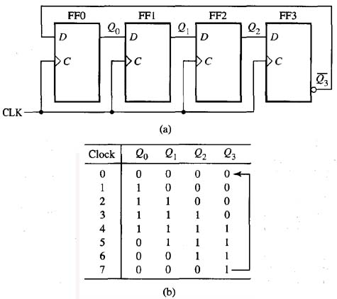
Above: Fig. 17: (a) Four edge-triggered D flip-flops are connected to form a Johnson counter. Notice the Q output of the flip-flop is connected to the D input of the first flip-flop. (b) The sequence table for the four-bit Johnson counter.
At this point each flip-flop is set and has the value of 1, so when the next clock pulse is received FF3 sends its Q (Q NOT) output (0) back to FF0 so that the four flip-flops show a value of 0111. During the next steps, each flip-flop is reset to 0 in sequential order until the value of 0001 occurs. At this point the next time the shift register is pulsed, the count starts over again.
From this example, notice that the four-bit Johnson counter counts values 0-7. If a fifth flip-flop is added, the Johnson counter could count values 0-9, and each additional flip-flop in the counter allows the count to move up by a total of two.
The Ring Counter
The ring counter is similar to the Johnson counter except the Q output of the last flip-flop rather than the Q is sent back to the first flip-flop. The inter-stage connections and the clock arrangement are the same as the Johnson counter so that the value of each flip-flop is shifted from left to right through each of the flip- flops. Fig. 18a shows a ten-bit ring counter that uses ten flip-flops. Fig. 18b shows the sequence table for the ten bits.
From this example, notice that when a 1 is presented to the first flip- flop, it will be shifted through all of the flip-flops in sequence as the clock is pulsed, which allows the counter to count one decimal value for each flip-flop. The ring counter does not require a decoding gate for decimal conversion, since there is an output for each of its each decimal numbers.
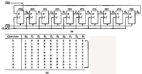
Above: Fig. 18: (a) Ten flip-flops connected to create a ring counter. Notice the Q output of the last flip-flop is fed back to the 0 input of the first flip-flop. (b) The sequence table for a ten-bit ring counter.
The Gray Code Counter
The gray code counter provides values that represent the gray code, which is a non-arithmetic system that does not have weights assigned to each bit. Instead it shows only a single bit change from one code number to the next. This code is used primarily in shaft position encoders in robots and other types of motion control. The problem with binary code and binary coded decimal systems is that more than one bit may change from a 0 to 1 or from a 1 to a 0 at the same time. This causes a problem in devices such as shaft encoders when the encoder stops at a position that is on a line between two adjacent sectors. Since the encoder stops on the line rather than exactly on a sector, it must judge which sector to select. Tithe problem occurs between values 1-2 or 4-5, it does not cause a lot of harm, but if the value of the sectors is near to the most significant values, the error is multiplied by the value weight of the two sectors.
The gray code eliminates this problem by changing the state of only one bit at a time as the value increases or decreases. Fig. 19 shows an example of the four-bit values of the gray code and compares it with the traditional binary code for the corresponding decimal values 0-15. From this figure notice that the gray code and the binary code for the decimal number 0 are both 0000, and for the decimal number 1 they are both 0001. When number 2 is displayed, observe that in the binary system the value in the 1 column changes to a 0 and the value in the 2 column changes to a 1. In the gray code, only the value in the second- bit column changes, while the value 1 in the first-bit column remains the same.
Notice in the binary system when the decimal number changes from a 3 to a 4, the values in the 1, 2, and 4 columns all change. In the gray code, only the value in the third binary column changes. When the binary system changes from the value 7 to 8, the bits in all four columns must change, and in the gray code only the bit in the fourth binary column changes. As the numbers in the binary system increase, more columns must change as the numbers increase or decrease, which increases the possibility of the encoder landing between more sectors. With the gray code, the largest possible error is one bit, and since the values are not weighted, this reduces the total encoder error more significantly.
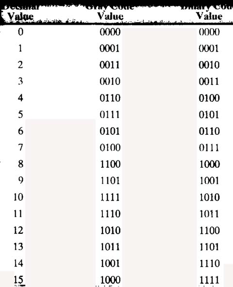
Above: Fig. 19: Gray code and binary code equivalents for decimal values 0-15.

