AMAZON multi-meters discounts AMAZON oscilloscope discounts
The CSIR motor can be used for a wider variety of applications where more motor starting torque is required than a split-phase motor can supply. These applications include direct-drive water pumps, air compressors, and larger conveyors. The capacitor start motor is also used to drive hermetic compressors for single-phase air- conditioning systems on rooftops and in window units. The hermetic compressor is the sealed motor that is used to drive the refrigeration pump. Since this is a direct-drive application, the CSIR motor is generally used. The split-phase motor may be used on the smaller hermetic motors and systems that use a capillary tube for their refrigerant metering valve.
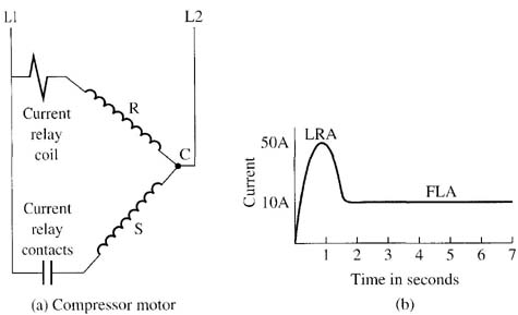
Since the compressor is hermetically sealed, it's not practical to place the end switch inside the compressor housing with the motor because it's likely to wear out and require replacement. It's also dangerous to allow the end switch to be mounted inside the compressor housing because it may cause a spark that could ignite fumes from the oil that is used in the compressor for lubrication and cause an explosion. Since an end switch can't be used, a current relay is used to disconnect the start winding after the motor starts. An electrical diagram of the current relay is provided in Fig. 1.

Above: Fig. 1: (a) Diagram of a current relay connected to a hermetic-type
compressor motor. The current relay is used in place of a centrifugal
switch since the compressor is a sealed motor. The current relay provides
the same function as the centrifugal switch. (b) A diagram of locked-rotor
current (LRA) and full-load cur rent ( FLA) for the compressor motor.
The current relay is generally connected directly on the motor terminals. Note from the electrical diagram that the current relay consists of a coil and a set of contacts. The coil is connected between terminals L1 and MR and the NO contacts are connected between terminals L1 and S. Note that the motor is shown as a run winding and a start winding. One end of the run winding and one end of the start winding are connected together at the right side and this point is identified as the common (C).
The diagram shows the current relay connected to the motor. Notice that the coil of the current relay is connected in series with the run winding and it will remain in this part of the circuit even when the motor is running. The contacts of the current relay are connected in series with the start winding. Since a start capacitor is used with this motor, the contacts (terminal S) of the relay are connected to the start capacitor and the other terminal of the start capacitor is connected to the start winding of the motor.