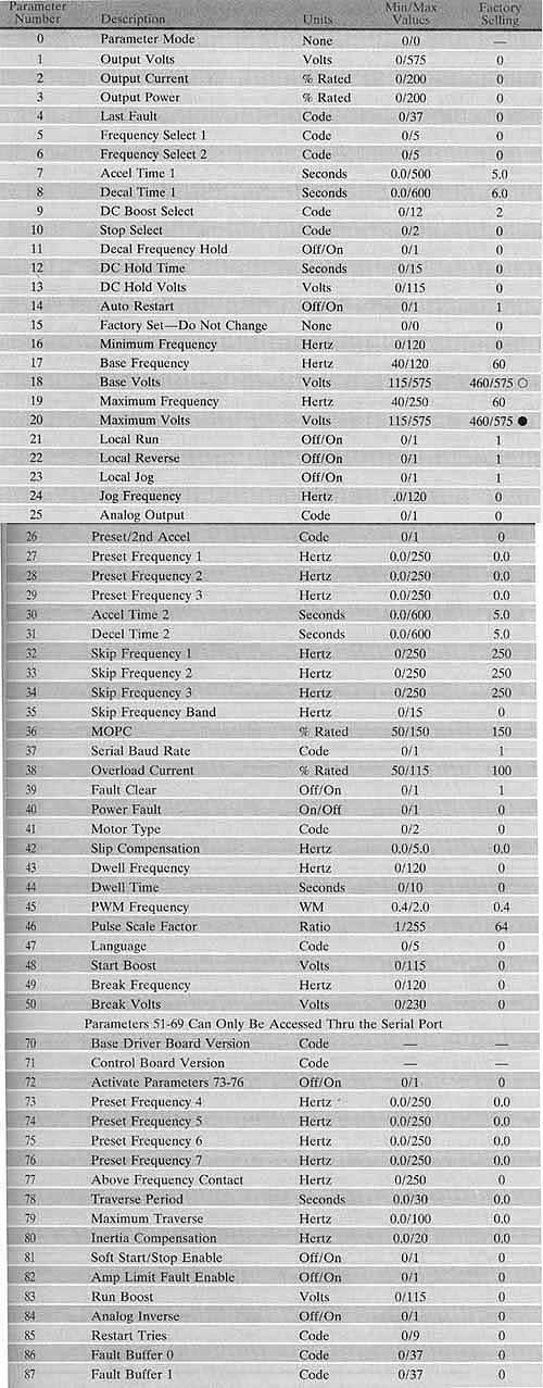
Variable-frequency drives have had the ability to provide features such as ramp up speed, ramp-down speed, boost voltage, and braking functions since they were first designed. Prior to having a microprocessor, these features and functions were designed into the op amp circuits that controlled the drive and were enabled by the placement of jumpers or the setting of dip switches. After microprocessor chips were integrated into the drive, these features have become programmable and in many cases they have become proportional so that you can ask for braking, but you can limit the braking to 60% for 3 seconds. If you select ramp up, you can select more than one ramp speed. Then you can integrate the selection with an external switch so that the ramp speed can be selected by external conditions. The numbers that are programmed into the drive to select these features are called parameters. The type and number of parameters will vary from drive to drive. The Allen-Bradley 1336 drive has 89 parameters while the Allen-Bradley 1305 drive has 136 parameters. The table below shows a typical list of parameters for a variable-frequency drive.
 The
drive has a set of standard values to be used for the parameters. These
parameters are called the default settings or factory settings. It is
important to record the actual parameter settings if they are different
from the factory settings, so that the proper settings can be put into
the drive if it's ever removed and replaced with a new one. The parameters
provide a means to customize the drive to any specific application. Some
manufacturers provide software that can be used on a portable computer
to save and load the parameters from a drive. The parameters can also
be saved and loaded from the PLC program, which means they can also be
changed while the system is in operation to provide custom parameters
for multiple recipes.
The
drive has a set of standard values to be used for the parameters. These
parameters are called the default settings or factory settings. It is
important to record the actual parameter settings if they are different
from the factory settings, so that the proper settings can be put into
the drive if it's ever removed and replaced with a new one. The parameters
provide a means to customize the drive to any specific application. Some
manufacturers provide software that can be used on a portable computer
to save and load the parameters from a drive. The parameters can also
be saved and loaded from the PLC program, which means they can also be
changed while the system is in operation to provide custom parameters
for multiple recipes.
The parameters can be described in groups by their function. Examples of these groups include metering, setup, advanced setup, frequency settings, diagnostics, faults, and process displays. Examples of the setup group include minimum frequency and maximum frequency. This allows the minimum and maximum frequency to be fixed so that the motor doesn't run less than the minimum value and more than the maximum value.
Another setup parameter is acceleration time, which determines the acceleration ramp. For example, if you select the ramp time as 10 seconds, the drive will increase the frequency proportionally from the programmed minimum frequency to the programmed maximum frequency in 10 seconds. If you wanted the motor to ramp up to speed more quickly, you would shorten the ramp time. If you wanted the motor to ramp up more slowly, you would increase the ramp time. Most drives have more than one acceleration ramp parameter and each ramp is enabled to the input switches that were previously discussed. This means that you could have up to three acceleration ramps that would be selected by switch 1, 2, or 3. The deceleration time is also programmable. Three deceleration ramps are available for this drive.
Another setup parameter available for the drive is overload current limit. This parameter will act like a programmable fuse. You can select any value from 100-115. The other variable that operates with the overload current is the amount of time this current can exist. Since the drive is controlled by a microprocessor, it monitors the current and voltage and turns off the drive if these values become excessive.
The drive also provides metering parameters. These can be integrated with protection, display, and fault functions. Most drives have displays that are built into the face of the drive. The technician can use the display on the face of the drive to observe the amount of input voltage, the amount of current, the frequency, the temperature, the output voltage, and the last fault that was recorded.
Advanced setup parameters include the type of braking the drive will use. The choice for this parameter is no braking (coasting to a stop) or braking, and the amount of braking voltage and the amount of time the braking voltage should be applied are determined. Another advanced setup parameter is called DC boost voltage, which is DC voltage that can be applied with AC frequency during starting or at times when the motor needs more torque. The DC boost voltage makes the magnetic field in the motor stronger to reduce the amount of slip the motor has. This will allow the motor to provide additional power in applications where more starting torque is needed or when more torque is needed during specific loading conditions.
The drive has the ability to test hundreds of points in its circuit boards for changes in voltage, current, frequency, and temperature. The present value of each of these variables at the input and output stages of the drive can be compared against the value set into the parameter. If the value is exceeded, the drive can indicate each occurrence with a fault code. The drive also changes the state of contacts that can be used to enable a fault indicator lamp or horn. If the fault has occurred, it will be stored in the drive where it can be brought to the display by pressing a series of keys on the front panel of the drive. The serial port connection provides a method to send the fault codes to an external controller such as a PLC where they can be logged with the date and time they occurred and they can also be printed as they occur. Some drives have the capacity to store multiple faults so that the technician can review the last five faults. This provides a means to detect and store multiple faults if more than one problem occurs during the fault condition. Typical fault conditions are low voltage, high voltage, high current, and over-temperature.