In
newer drives, such as the 1336 PLUS AC Drive shown on the left, the transistors
may be replaced by insulated gate bipolar transistors (IGBTs). The IGBTs
are used because they can be switched on and off at much higher frequencies
-- aka the switch frequencies -- that don't conflict with other signals.
The higher frequencies are also used outside of the audible range for
humans, so the drive will not emit a hum that humans can hear. Typical
switch frequencies are 3KHz to 4KHz. (With an older, SCR-based drive,
switch frequencies are 250 to 500 Hz). As one can imagine, the higher
the switch frequency, the smoother the output waveform and the higher
the resolution. However, higher switch frequencies decrease the efficiency
of the drive because of increased heat in the power devices.
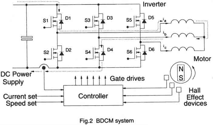
The diagram below shows two pairs of IGBTs used to produce two phases of a typical output section for a variable-frequency drive using IGBTs instead of bipolar transistors. From this section one can see that one IGBT of each pair is connected to the positive bus and a second is connected to the negative bus. The IGBTs operate similarly to the transistors in that they are cycled on and off at high frequencies within the overall waveform of a sine wave.

above: Insulated gate bipolar transistors
(IGBTs) connected to the output stage of the variable-frequency drive.
The IGBTs are used instead of traditional bipolar motor transistors in
newer drives. Image courtesy of Philips electronics.