The diagram below shows a common waveform for a pulse-width modulation (PWM) circuit in the AC variable-frequency drive. The transistors in the PWM circuit are switched on and off approximately 12 times each half-cycle. The on and off cycles create the overall frequency waveform for the output signal. The output waveform of the PWM section looks like a traditional three-phase signal to the motor. If one places an isolated-case oscilloscope across any two of the output leads of the drive, one will see a signal that looks similar to the one in the diagram.
If one is using a digital voltmeter to measure the output voltage on a variable-frequency drive, one must be aware that some digital voltmeters will not read the AC voltage from this section accurately because of the switching frequency of the transistors. The digital voltmeters tend to read the drive's output voltage higher than it actually is because the voltmeter may be fast enough to sample some of the individual waveforms created when the transistors are switched on and off rapidly. An analog meter may show the voltage more accurately because the needle can't change as fast as the transistor is switched on and off. For this reason some drive manufacturers provide an LED display to show an accurate voltage reading right on the face of the drive.
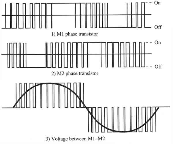
Output waveform of the PWM
section of the variable-frequency drive. Notice all of the points
where the transistor is switched on and off inside each half-wave.
Rockwell/Allen-Bradley.