AMAZON multi-meters discounts AMAZON oscilloscope discounts
..
1. Introduction
As we had seen in the previous section, grounding of supply system neutral fulfills two important functions.
- It provides a reference for the entire power system to the groundmass and establishes a path for flow of currents to ground whenever there is a failure of insulation so that the fault can be detected by circuit protective devices and isolated.
- It ensures that in the event of an accidental connection of live parts to a conducting metallic enclosure, any person coming into contact with the enclosure does not experience dangerously high voltages. This is done by bonding the enclosure to the ground so that the enclosure's potential is firmly 'clamped' to that of the ground. Also, bonding of all exposed metal parts in a building and connecting them to ground creates an equipotential environment where all such parts will be essentially at the same potential as the ground.
In this section, we will learn about the various types of grounding an electrical system and their relative advantages. As you may recall from the previous section, grounding of both source and the consumer equipment is necessary. What we will see in this section is about the grounding of the power source.
Note: We will be discussing in this as well as in the subsequent sections electrical systems of three-phase configuration since for all practical purposes, this is the only configuration that utilities all over the world adopt. Systems of single-phase configuration will, however, be used in illustrations for simplicity. FIG. 1 shows the various types of grounding methods that are possible.
The diagrammatic representation of these different grounding techniques and the equivalent impedances are shown in FIG. 2. We will go through in detail about each method in the subsequent paragraphs.
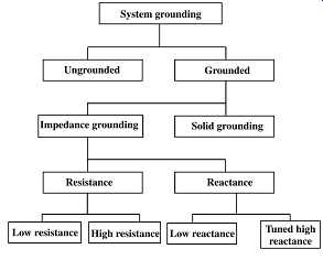
FIG. 1 Grounding methods
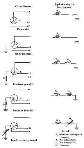
FIG. 2 Grounding techniques and equivalent impedances
Grounding of power supply system neutral 15
2. Ungrounded systems
As discussed in Section 1, providing a reference ground in an electrical system is essential for safe operation. But there are certain cases in which a system can be operated without such a reference.
By definition, an electrical system, which is not intentionally connected to the ground at any point, is an ungrounded system. However, it should be noted that a connection to ground of sort does exist due to the presence of capacitances between the live conductors and ground, which provides a reference. But these capacitive reactances are so high that they cannot provide a reliable reference. FIG. 3 illustrates this point. In some cases, the neutral of potential transformer primary windings connected to the system is grounded, thus giving a ground reference to the system.
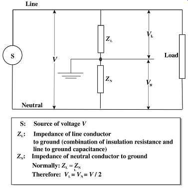
FIG. 3 A virtual ground in an ungrounded system
It may be noted that normally the capacitance values being equal to the lines L1 and L2 are roughly at a potential equal to half the voltage of the source from the ground (it is possible to demonstrate this by measurement of a high-impedance device such as an electrostatic type of voltmeter). The main advantage cited for ungrounded systems is that when there is a fault in the system involving ground, the resulting currents are so low that they don’t pose an immediate problem to the system. Therefore, the system can continue without interruption, which could be important when an outage will be expensive in terms of lost production or can give rise to life-threatening emergencies.
The second advantage is that one need not invest on elaborate protective equipment as well as grounding systems, thus reducing the overall cost of the system. (In practice, this is however offset somewhat by the higher insulation ratings which this kind of system calls for due to practical considerations.)
The disadvantages of such systems are as follows:
• In all but very small electrical systems, the capacitances, which exist between the system conductors and the ground, can result in the flow of capacitive current at the faulted point which can cause repeated arcing and buildup of excessive voltage with reference to ground. This is far more destructive and can cause multiple insulation failures in the system at the same instant.
• The second disadvantage in practical systems is that of detecting the exact location of the fault, which could take far more time than with grounded systems.
This is because the detection of fault is usually done by means of a broken delta connection in the voltage transformer circuit ( FIGs. 4a and b). This arrangement does not tell where a fault has occurred and to do so, a far more complex system of ground fault protection is required which negates the cost advantage we originally talked about.
• Also, a second ground fault occurring in a different phase when one unresolved fault is present, will result in a short circuit in the system.
Due to these overwhelming disadvantages, very rarely, if ever, distribution systems are operated as ungrounded.
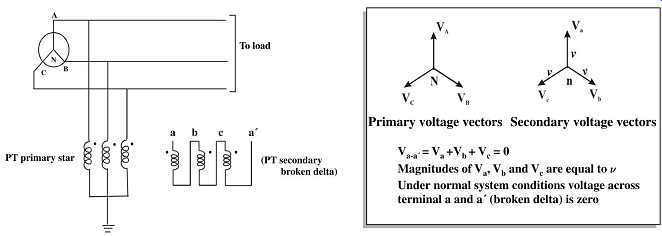
FIG. 4a Detection of ground fault using a broken delta connection - under
normal condition
3. Solidly grounded systems
As is evident from the name, a solidly grounded system is one where the neutral of the system is directly connected to ground without introducing any intentional resistance in the ground circuit. With appropriate choice of the type and number of grounding electrodes, it’s possible to obtain a very low-impedance ground connection, sometimes as low as 1 ohm. A solidly grounded system clamps the neutral tightly to ground and ensures that when there is a ground fault in one phase, the voltage of the healthy phases with reference to ground does not increase to values appreciably higher than the value under the normal operating conditions.
When there is an Earth fault in line A it assumes Earth Potential.
Therefore Voltage across PT primary windings become
ABBA, CCA V 0, V =V ,V =V =
Thus Secondary Vectors are
abba, cca V 0, V =V ,V =V =
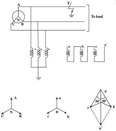
FIG. 4b Detection of ground fault using a broken delta connection - under
Ground Fault condition
The advantages of this system are:
• A fault is readily detected and therefore isolated quickly by circuit protective devices. Quite often, the protection against short circuit faults (such as circuit breakers or fuses) is adequate to sense and isolate ground faults as well.
• It’s easy to identify and selectively trip the faulted circuit so that power to the other circuits or consumers can continue unaffected (contrast this with the ungrounded system where a system may have to be extensively disturbed to enable detection of the faulty circuit).
• No possibility of transient over-voltages.
The main disadvantage is that when applied in distribution circuits of higher voltage (5 kV and above), the very low ground impedance results in extremely high fault currents almost equal to or in some cases higher than the system's three-phase short circuit currents.
This can increase the rupturing duty ratings of the equipment to be selected in these systems.
Such high currents may not have serious consequences if the failure happens in the distribution conductors (overhead or cable). But when a fault happens inside a device such as a motor or generator such currents will result in extensive damage to active magnetic parts through which they flow to reach the ground.
For these reasons, use of solid grounding of neutral is restricted to systems of lower voltage (380 V/480 V) used normally in consumer premises. In all the other cases, some form of grounding impedance is always used for reducing damage to critical equipment components.
4. Impedance grounding using neutral reactor
In this method of grounding, an inductor (also called a grounding reactor) is used to connect the system neutral to ground. This limits the ground fault current since it’s a function of the phase to neutral voltage and the neutral impedance. It’s usual to choose the value of the grounding reactor in such a way that the ground fault current is restricted to a value between 25 and 60% of the three-phase fault current to prevent the possibility of transient over-voltages occurring. Even these values of fault current are high if damage prevention to active parts (as seen above) is the objective.
5. Resonant grounding using neutral reactor
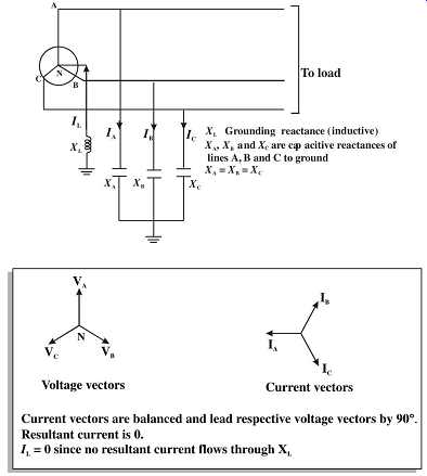
To avoid the problem of very high ground fault currents, the method of resonant grounding can be adopted. Resonant grounding is a variant of reactor grounding with the reactance value of the grounding reactor chosen such that the ground fault current through the reactor is equal to the current flowing through the system capacitances under such fault condition. This enables the fault current to be almost canceled out resulting in a very low magnitude of current, which is in phase with the voltage. This serves the objectives of low ground fault current as well as avoiding arcing (capacitive) faults, which are the cause of transient over-voltages. The action is explained in FIG. 5.
This type of grounding is common in systems of 15 kV (primary distribution) range with mainly overhead lines but is not used in industrial systems where the reactor tuning can get disturbed due to system configuration changes caused by switching on or off cable feeders (with high capacitive currents) frequently.
6. Impedance grounding through neutral resistance
This is by far the most common type of grounding method adopted in medium voltage circuits. The system is grounded by a resistor connected between the neutral point and ground. The advantages of this type of grounding are as follows:
• Reducing damage to active magnetic components by reducing the fault current.
• Minimizing the fault energy so that the flash or arc blast effects are minimal thus ensuring safety of personnel near the fault point.
• Avoiding transient over-voltages and the resulting secondary failures.
• Reducing momentary voltage dips, which can be caused if, the fault currents were higher as in the case of a solidly grounded system.
• Obtaining sufficient fault current flow to permit easy detection and isolation of faulted circuits.
Resistance grounding can again be sub-divided into two categories, viz. high-resistance grounding and low-resistance grounding.
High-resistance grounding limits the current to about 10 A. But to ensure that transient over-voltages don’t occur, this value should be more than the current through system capacitance to ground. As such, the applications for high-resistance grounding are somewhat limited to cases with very low tolerance to higher ground fault currents. A typical case is that of large turbine generators, which are directly connected to a high voltage transmission system through a step up transformer. The capacitance current in generator circuits is usually very low permitting values of ground fault currents to be as low as 10 A. The low current ensures minimal damage to generator magnetic core thus avoiding expensive factory repairs. FIG. 6 illustrates a practical case of grounding the neutral of a generator of this type.
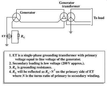
FIG. 6 Grounding of a turbine generator neutral through a high neutral
resistance.
On the other hand, a low-resistance grounding is designed for ground fault currents of 100 A or more with values of even 1000 A being common. The value of ground fault current is still far lower than three-phase system fault currents. This method is most commonly used in industrial systems and has all the advantages of transient limitation, easy detection and limiting severe arc or flash damages from happening.
7. Point of grounding
In most three-phase systems, the neutral point at source (a generator or transformer) is connected to ground. This has the advantage of minimum potential of the live terminals with reference to ground.
In the case of generators, which are almost always star (wye) connected, the neutral point is available for grounding. However, in the case of transformer substations, a neutral may not always be available as the winding may be delta connected. In such cases, it will be necessary to obtain a virtual neutral using a device called grounding transformer.
Grounding transformers are generally of two types viz. zig-zag connected transformer with no secondary winding and a wye-delta transformer. FIG. 7 shows a zig-zag grounding transformer.
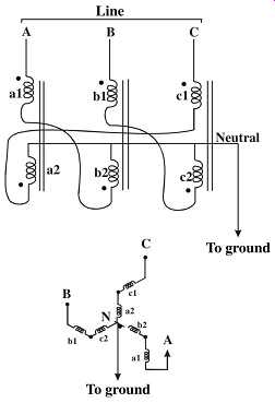
FIG. 7 Zig-zag grounding transformer
The transformer primary winding terminals are connected to the system, which has to be grounded. The neutral point of the transformer is grounded solidly or through an impedance depending on the type of grounding selected. Under normal conditions, the transformer behaves like any other transformer with open circuited secondary (no-load) and draws a small magnetizing current from the system. The impedance of the transformer to ground fault (zero sequence) currents is however extremely small. When one of the lines develops a ground fault, the current is only restricted by the grounding impedance. Thus, the system behaves virtually in the same manner as any system with grounded source neutral. FIG. 8 shows this behavior. The ground fault current flowing in the faulted line divides itself into three equal parts flowing through each phase winding of the transformer.
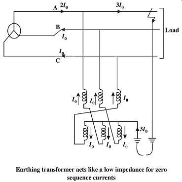
FIG. 8 Behavior of a zig-zag connected transformer during a ground fault
The other type of grounding transformer is a wye-delta connected transformer. The primary winding terminals of the transformer are connected to the system, which is to be grounded, the neutral of the primary is connected to the ground and the secondary delta is either kept open or can be connected to a three-phase three-wire supply system as required (refer to FIG. 9). This type of transformer too presents a low-impedance path to the flow of zero sequence currents due to the circulating path offered by the secondary delta winding. This enables the ground fault current to flow through the primary and to the ground through the grounding impedance. FIG. 10 illustrates this action.
British Standard BS: 7671:2000 (IEE Wiring regulations) discusses the grounding of low-voltage installations in detail and has provided a method of classifying supply systems based on the type of grounding adopted as well as the method used to extend the system ground to consumer installations. The standard also discusses the comparative merits of the different types of systems for specific applications (refer to Section A for details of this classification).
8. Other challenges
In the above discussions, we dealt with systems having a single source. However, when more than one source is involved (such as multiple generators or a mix of generators and transformers), grounding of neutrals becomes even more of a challenge. The guiding principles are still the same, viz. the need for limiting the fault current to safe but easily detectable values and the prevention of transient over-voltages during a ground fault.
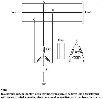
FIG. 9 Star-delta grounding transformer
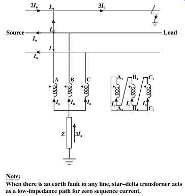
FIG. 10 Behavior of star-delta grounding transformer during system ground
faults
In the case of power distribution systems with several voltage levels separated by transformers, it’s necessary to establish neutral grounding for each individual system, taking into consideration the principles cited above and the characteristics of each system.
Neutral grounding of electrical systems within large mobile equipment having their own step down transformers presents further complexities. These are however beyond the scope of this guide and are not therefore elaborated.
9. Summary
In this section, we discussed various types of grounding electrical systems and the considerations that govern the choice. We have also seen how a virtual neutral point can be established through indirect means using a grounding transformer. Different types of supply systems based on neutral wiring practices were reviewed.
