AMAZON multi-meters discounts AMAZON oscilloscope discounts
...
1 Introduction
The practice of grounding of electrical systems is almost as old as the development and widespread use of electric power itself. In this guide, we will take a look at the need for adopting good grounding practices at both the source of power (a generator or a transformer substation) and the consumer premises. We will study various methods of grounding of electrical systems and make a comparison of their effectiveness. We will learn about electric shock and how to prevent electrical accidents by timely detection and isolation of faulty equipment. We will discuss the effect of lightning on electrical systems and the means of protecting the systems from damage by safely conducting away the surges caused by lightning strokes into ground. We will learn the method of establishing reliable ground connections, to predict by calculating the earth resistance and the methods for measurement of earth resistance of grounding systems.
We will also review why even non-electrical gear parts of certain types of machinery will have to be connected or bonded to ground to prevent accumulation of static charges, which would otherwise cause sudden and destructive spark-over.
We will also review the practices adopted for grounding and bonding in consumer premises and their importance in modern day systems with a lot of sensitive electronic equipment (which create as well as are affected by phenomena such as surges, electrical noise, etc.). Further, we will detail the importance of shielding of signal wires and establishing a zero signal reference grid in data processing centers. We will study the generation of harmonics and how they affect electrical equipment, as well as the means to avoid them. We will learn about power quality and the role of uninterrupted power supply (UPS) systems in overcoming some of the power supply problems and discuss various possible configurations of static UPS systems and the issues pertaining to the grounding of UPS fed systems.
Note: The terms earth and ground have both been in general use to describe the common signal/power reference point and have been used interchangeably around the world in the electrotechnical terminology. The IEEE Green Guide, however, presents a convincing argument for the use of the term ground in preference to earth. An electrical ground need not necessarily be anywhere near the earth (meaning soil). For a person working in the top floor of a high-rise building, electrical ground is far above the earth.
In deference to this argument, we will adopt the term ground in this manual to denote the common electrical reference point.
2 Basics of grounding
Grounding serves the following principal purposes:
• It provides an electrical supply system with an electrical reference to the groundmass. By connecting a particular point of the supply source to the ground (such as the neutral of a three-phase source), it’s ensured that any other point of the system stays at a certain potential with reference to the ground.
• A metallic surface of the enclosure of an electrical system is grounded to ensure that it stays at ground potential always and thus remains safe to persons who may come into contact with it.
• It provides a low-impedance path for accumulated static charges and surges caused by atmospheric or electrical phenomenon to the ground thus ensuring that no damage is caused to sensitive equipment and personnel.
Electrical systems were not always grounded. The first systems were ungrounded ones with no ground reference at all. Even though such systems still exist in specific areas, they are the exceptions rather than the rule and by and large, some form of grounding is adopted for all power systems. We all know that the insulating layer around the current carrying conductors in electrical systems is prone to deterioration. When a failure of insulation takes place due to aging, external factors or due to electrical or thermal stress, it’s necessary to detect the point of failure so that repairs can be undertaken. In a system that has no ground reference at all, it’s not easy to correctly pinpoint the faulted location.
Refer to FIG. 1a, which shows such a system. It can be seen that due to the absence of a conducting path through ground, the fault remains undetected. If, however, a second fault occurs in the unaffected line at some other point in the system, it can cause a shorting path and results in the flow of high magnitude fault currents that can be detected by protective devices.
To detect the first fault point as soon as it happens without waiting for a second fault to develop, we ground one of the two poles of the source S (refer FIG. 1b). The pole that is grounded is generally called the neutral and the other, 'line'. It would be of interest to note that the connection between neutral and earth is only at the source. The return current from the load flows only through the neutral conductor back to the source. For this reason, the neutral is always insulated from ground and usually to the same degree as the line conductor.
When there is an insulation failure in the line conductor, a high current flows through the electrical circuits and through the ground path back to the source and depending on the resistance of the ground path, the current flow in this path can be detected by appropriate protective equipment.
Thus, one of the primary purposes of grounding is to permit easy detection of faults in electrical systems by providing a path for the flow of currents from the fault point through the ground (and sometimes the earth mass) back to the neutral point of the source. Now let us take a step further and see as to why it’s necessary for this ground reference to be extended to the consumer installation. While FIG. 1b shows that the source is grounded, it does not indicate another point of connection to ground. However, in practical systems, the fact that a failure of insulation takes place does not mean that a ground connection is automatically established. This can only be done if the point of failure is connected to ground through a low-impedance ground path. Such a path is created using a reference ground bus at the consumer end and connecting the metallic housing of all electrical equipment to this bus (refer FIG. 2).
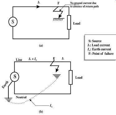
FIG. 1 (a) Fault in ungrounded system, (b) Effect of grounding the neutral
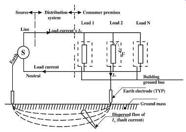
FIG. 2 Fault current flow in a grounded system
In fact, it’s preferable to have the ground terminal of a low voltage consumer installation directly connected to the neutral of the source to ensure that the ground fault current has a low-impedance path not involving the earth mass. It’s difficult to predict accurately the resistance of groundmass to the flow of currents and hence except for high voltage systems, the emphasis will be on obtaining direct metallic continuity. It should be noted that the neutral of the electrical load is isolated from the ground, and the connection between neutral and ground is still at the source point only. We will cover the different ways in which the neutral and ground references are distributed by a supply system to its consumers (giving rise to different categories of systems). We will also see in a subsequent section as to how the grounding of metallic enclosures of current-carrying equipment fulfills another important function: that of making the systems safe for operation by human beings without fear of electrocution in the event of an insulation failure in the live parts.
3 Bonding
Bonding refers to the practice of connecting various grounding systems as well as non current-carrying metal or conductive parts together so that there will be no potential difference between different accessible conducting surfaces or between different grounding systems. Such potential difference can be hazardous if a person comes into contact simultaneously with two surfaces between which a potential difference exists.
Equipotential bonding achieves potential equalization between all surfaces, which are thus bonded. This topic is covered in detail in Section 3.
Another problem, which can occur in the absence of bonding, is that the potential difference can cause equipment damages when two parts of sensitive equipment are connected to systems, which can acquire different potentials. The currents that flow through inter-system capacitances can cause damage to sensitive components and printed circuit boards. This type of problem generally occurs when ground current surges happen as a result of lightning discharges or other atmospheric phenomena. Case studies involving this principle have been illustrated in a subsequent section.
4 Lightning and its effect on electrical systems
Lightning is the result of the development of cells of high potential in cloud systems as a result of charge accumulation and the consequent discharge between cells carrying opposing charges or to ground. The high potential difference causes ionization of air between these cells and ground, which then becomes conductive and allows a short burst of extremely high current to flow resulting in instantaneous dissipation of accumulated charge. Usually, the first lightning strike allows further multiple strikes along the same path when the charges from nearby cloud cells also discharge through it to ground.
The lightning strokes to ground usually involve some tall structure or object such as a tree. While the stroke on a conducting structure (that provides an extremely low impedance path to ground) does not result in major damages, the results are disastrous in the case of structures that are not fully conductive. The damage occurs mainly because of extreme heating that takes place due to high current flowing through the object. This, in turn, causes any moisture present in the structure to evaporate suddenly. The resulting explosive release of steam causes extensive damage to the object. For example, in a tree that suffers a lightning stroke, the moist layer under its bark vaporizes instantaneously which causes the bark to fly away. A more serious result can occur if the stroke occurs near or on a container carrying flammable materials. The high temperatures can ignite the flammable materials causing severe explosions and secondary damages. Such structures need special protection against lightning strokes.
Of greater interest to us in this guide is the effect lightning discharge has on electrical systems and how electrical equipment and installations can be protected against damage.
These will be dealt in detail in a subsequent section.
5 Static charges and the need for bonding
Certain types of non-electrical machinery can cause a buildup of static charge during their operation and this charge accumulates on the surface of the equipment parts ( For example, a flat rubber belt around two metal pulleys, which is a very common type of motive power transmission, generates a lot of static electricity). When a sufficient amount of charge is built up, a spark-over can occur between the charged part and any grounded body nearby. FIG. 3 illustrates the principles involved.
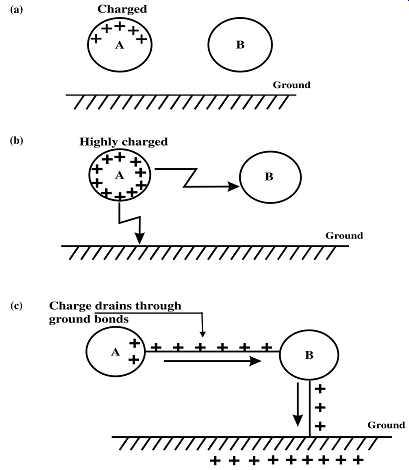
FIG. 3 Example of static electricity buildup and prevention
Body A has a positive charge while no charge is present on the nearby body B, both of which are insulated from the ground ( FIG. 3a). Let us now assume that body B is connected with ground. When body A acquires a sufficient quantum of charge that can cause breakdown of the medium separating A and B or A and ground, it will result in a spark discharge ( FIG. 3b). Such spark-over carries sufficient energy that can cause explosions in hazardous environments and fires in case combustible materials are involved. It’s therefore necessary to provide bonding of the parts where charge buildup can occur by suitable metallic connections to earth. Bonding bodies A and B with a conducting metallic wire causes the charge to flow on to body B. This causes the charge to continuously leak into the ground so that buildup of dangerously high voltages is prevented (refer to FIG. 3c). Some of the practical cases of static buildup that occur in industrial and consumer installations and ways and means of avoidance will be dealt in further detail in a subsequent section.
6 Ground electrodes and factors affecting their efficacy
A common thread in the foregoing discussions is the need for a good ground connection in power sources, consumer installations and for structures prone to lightning strokes.
The connection to groundmass is normally achieved by a ground electrode. Several types of ground electrodes using different materials, physical configurations and designs are in widespread use and follow usually the local standards that govern electrical installations. In most standards, a metallic rod driven into the ground to a depth where adequate moisture is available in the soil throughout the year in both wet and dry seasons is recommended for use as a ground electrode. A typical electrode is shown in FIG. 4.
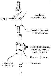
FIG. 4 A typical ground electrode used in electrical installations
The performance of such electrodes (considering the ground resistance of the electrode as an indicator) depends on the type of soil, its composition, conductivity, presence of moisture, soil temperature, etc. Several ground electrodes bonded together to form a cluster are usually provided for achieving satisfactory results. The general requirements that influence the choice of earth electrodes are as follows:
• The type of soil where the grounding is carried out (in particular, its electrical resistivity).
• The need for achieving minimum acceptable earth resistance appropriate to the installation involved.
• The need to maintain this resistance all round the year in varying climatic conditions.
• Presence of agents that can cause corrosion of elements buried in ground.
The electrode design and methods of installation will be dependent on these requirements. These will be taken up in detail in a later section.
To improve the conductivity of ground electrodes, several forms of electrode construction are in use in which the layer of soil surrounding the electrode is treated with chemical substances for improving the conductivity. These are known as chemical electrodes. The basic principle of these electrodes is the use of substances that absorb moisture and retain it over long periods. These are packed as backfill around the electrode. Materials containing carbon (charcoal/coke) and electrolyte salts such as sodium chloride are typically used as backfill. FIG. 5 shows such an electrode construction. It may also be noted that in this construction, a provision has been made to add water externally to keep the backfill material wet during prolonged dry weather conditions.
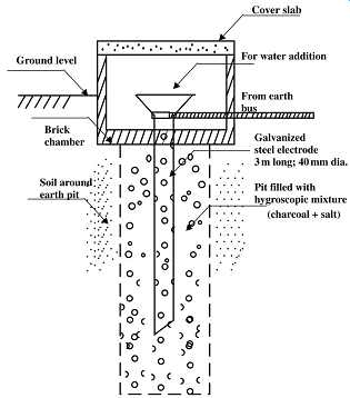
FIG. 5 A typical chemical ground electrode
It will also be evident from the above discussions that being a critical factor in the safety of installation and personnel, the grounding system will have to be constantly monitored to ensure that its characteristics don’t drift beyond acceptable limits. The practical methods adopted for measurement of soil resistivity and the resistance of a ground electrode/grounding system will also be covered in later sections.
7 Noise in signaling circuits and protective measures such as shielding
Noise in communication and signaling circuits is an issue needing careful consideration while planning and installing a system. Noise can be due to improper earthing practices.
It may also arise from surges due to external or internal causes (explained in the previous section) and by interference from other nearby circuits. Incorrect earthing can result in noise due to ground loops. FIG. 6 is an example of such a situation.
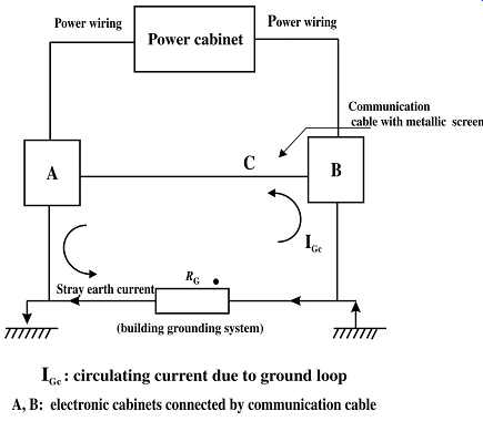
FIG. 6 Ground loop problem
A and B are two electronic data processing systems with a communication connection C between them. C is a cable with a metallic screen bonded to the enclosures of A and B. A and B are grounded to the building grounding system at points G1 and G2. RG is the resistance between these points. G1 and G2 are thus forming a ground loop with the cable screen and any current in the ground bus between G1 and G2 causes a current to flow through the communication cable screen, in turn resulting in spurious signals and therefore malfunction.
Multiple grounding by bonding of the electrical ground wire to the conduits and the conduits themselves with other building structures and piping is done in electrical wiring to get a low ground impedance and it has no adverse effect on power electrical devices. In fact, many codes recommend such practices in the interest of human safety. However, as shown in the above example, the same practice can cause problems when applied to noise-sensitive electronic equipment.
Noise can be due to galvanic coupling, electrostatic coupling, electromagnetic induction or by radio frequency interference. Both normal signals and surge as well as power frequency currents can affect nearby circuits with which, they have a coupling. Design of certain types of signal connections has an inherent problem of galvanic coupling.
Electrostatic coupling is unavoidable due to the prevalence of inter-electrode capacitances especially in systems handling high-frequency currents. Most power electrical equipment produce electromagnetic fields. Arcing in the contacts of a switching device producing electromagnetic radiation or high-frequency components in currents flowing in a circuit setting up magnetic fields when passing through wiring are examples of such disturbances. This kind of disturbance is called electromagnetic interference (EMI). By and large, the equipment being designed these days have to conform to standards, which aim to reduce the propagation of EMI as well as mitigating the effects of EMI from nearby equipment by using appropriate shielding techniques. Shielding against electrostatic coupling and electromagnetic interference works differently and should be applied depending on the requirements of the given situation. The method of grounding the electromagnetic and electrostatic shield/screen is also important from the point of view of noise. Improperly grounded shield/screen can introduce noise into signaling and communication systems, which it’s to protect.
Since electronic equipment involve the use of high-frequency signals, the impedance of the grounding system (as against resistance, which we normally consider) assumes significance. The ground system design for such equipment must take the impedance aspect into consideration too.
These and other common problems faced in the electrical systems of today will be dealt in greater detail in subsequent sections. Remedial measures to avoid such phenomena from affecting sensitive circuits will also be discussed. We will also briefly touch upon the subject of harmonics, which are sometimes a source of noise. Harmonics are voltage/current waveforms of frequencies, which are multiples of the power frequency. Harmonics are generated when certain loads connected to the system draw currents that are not purely sinusoidal in waveform (such non-sinusoidal current waveforms can be resolved into a number of sinusoidal waveforms of the fundamental power frequency and its multiples). Many of the modern devices using semiconductor components belong to this type and constitute what are called non-linear loads. Harmonic current being of higher frequencies causes audible hum in communication circuits and can interfere with low amplitude signals. They also cause heating in equipment due to higher magnetic loss and failure of capacitor banks due to higher than normal current flow. We will cover the basic principles briefly in this guide.
8 Surge protection of electronic equipment
Modern day industries and businesses rely largely on electronic systems for their smooth functioning, be it industrial drives, distributed control systems, computer systems and networking equipment or communication electronics. These electronic devices often work with very low power and voltage levels for their control and communications and cannot tolerate even small over-voltages or currents. Induced voltages from nearby power circuits experiencing harmonic current flow can also cause interference in the systems carrying communication signals and can result in malfunctions due to erroneous or noisy signal transmission. Due to this sensitive nature of electronic and communication equipment, any facility that houses such equipment needs to have its electrical wiring and grounding systems planned with utmost care so that there are no unpredictable equipment failures or malfunction. Another problem is that of voltage spikes that occur in the power supply. Some of these may originate from the external grid but some others may originate from other circuits within the same premises. The result of such voltage/power surges is invariably the failure of the electronic device itself. A typical example of an external voltage disturbance is a lightning stroke near an overhead power transmission system. Such transients can also happen due to switching on or off large transformers. The transformers when charged draw a momentary inrush current and this can reflect as a voltage disturbance. Similarly, switching off an inductive load (say a coil energizing a contactor) causes a brief voltage spike due to the collapse of the magnetic field in the magnetic core. If other equipment are connected in parallel with the inductance (after the switching point), they will experience the surge. FIG. 7 shows the principle involved.
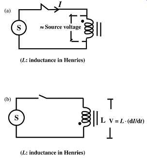
FIG. 7 Inductive load causing a transient surge
Any installation can be divided into various zones depending on the severity of surges to which equipment in the zone can be subjected. Surge protective devices and grounding are arranged in such a way that surge levels gradually get reduced from the most severe magnitudes in zone 0 to the highly protected zone 3, which houses the most sensitive and vulnerable systems. This is explained in Section 7 in detail. Different types of surge protective devices available and their application areas will also be touched upon.
9 UPS systems and their role in power quality improvement
Widespread use of process control/SCADA systems in industries and computers and communication equipment in business environment demands an uninterrupted power supply of good quality free from harmonics, voltage irregularities, etc. since these systems are sensitive to power interruptions and voltage/frequency excursions. Various uninterrupted power supply options of both electromechanical and static variety are available in the market. The electromechanical type of systems usually has a prime mover such as an engine-driven alternator. These systems have some form of intermediate energy storage, which permits the alternator to ride through power system disturbances and also provide the energy required to start the engine. However, the static inverter-fed UPS systems deriving standby power from a storage battery are the most commonly used type of system. In the present day systems, electronic UPS systems, switching elements of insulated gate bipolar transistors (IGBT) are employed to advantage. Besides making the switching circuit simple, they also permit the invertors to switch at very high frequencies. This in turn reduces noise, makes the systems more compact and with pulse width modulation techniques ensures a harmonic free output.
There are, however, a number of factors that come into play while selecting small and medium capacity UPS systems. This will be discussed in the concluding section of this guide. The issues relating to the grounding of these systems, as separately derived sources, have been extensively discussed in IEEE: 142 publications. We will discuss some of the commonly used UPS configurations in detail.
10 Case studies
This guide contains several facts that need attention in designing and implementing electrical and instrumentation systems. In order to illustrate the problems, which can be caused by not paying adequate attention to these aspects, a section outlining several case studies has been included. These case studies cover the problems encountered in various real life situations and have been illustrated in order to highlight the principles that have been dealt with in this guide.
11 Importance of local codes
While we covered, in the above discussion, the general physical principles involved in grounding of electrical systems and equipment, the actual practices adopted in different countries may vary. Different local codes approach the issue of grounding in their own different ways, taking into account factors such as the local environment, material availability and so on. All of them, however, aim to achieve certain common objectives, most important of them being the safety of personnel. Generation, distribution and use of electrical energy are subject to extensive regulatory requirements of each country such as the National Electrical Code (USA) and the Wiring Regulations (UK). It’s mandatory on the part of electricity suppliers and consumers to adopt the practices stipulated in these regulations and any deviations might cause the installation in question to be refused permission for operation. Thus, anyone engaged in the planning and design of electrical systems must be well versed with the applicable local codes and must take adequate care to ensure conformity to the codes in all mandatory aspects.
12 Summary
In this section, we had a broad overview of the need for grounding of electrical systems and the practices adopted for grounding. We covered the topics of lightning and static charges and learnt that precautions are needed to mitigate their effects. We discussed the configuration of a typical ground electrode and their general requirements. We had touched briefly on the need for proper protection of sensitive equipment to phenomena such as surges, harmonics and EMI. We discussed how inadvertent ground loops could affect the operation of sensitive signal circuits. We also reviewed the role of UPS systems in ensuring proper power quality. With this background information, we will proceed for a more in-depth discussion on these topics in the coming sections.