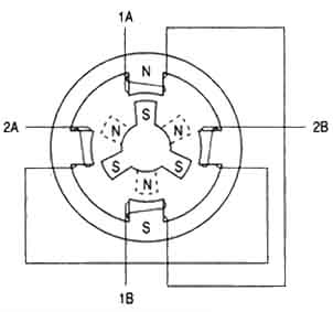
 above (Diagram 1): Figure illustrating the position of the six-pole rotor and four-pole stator of a typical stepper motor. |
Stepper motor were designed on the principles of electromagnetic theory in order to to make a motor turn a precise distance when a pulse of electric current is applied. Recall from basic physics that like poles repel and unlike poles attract. Diagram 1 (left) shows a typical cross-section a stepper motor's rotor and stator. Note that the stator (stationary winding) has four poles, and the rotor has six poles (three complete magnets). The rotor will require 12 pulses of electricity to move the 12 steps to make one complete revolution. In other words, the rotor will move exactly 30° for each pulse of electricity that the motor receives. The number of degrees the rotor will turn when a pulse of electricity is delivered to the motor can be calculated by dividing the number of degrees in one revolution of the shaft (360°) by the number of poles (north and south) in the rotor. In this stepper motor 360° is divided by 12 to get 30°. |
When no power is applied to the motor, residual magnetism in the rotor magnets will cause the rotor to detent or align one set of its magnetic poles with the magnetic poles of one of the stator magnets. Hence, the rotor has 12 possible detent positions. When the rotor is in a detent, it will have enough magnetic force to keep the shaft from moving to the next position. If you rotate the rotor by hand (with no power applied), the effect just noted makes the rotor feel like it's clicking from one position to the next .
When power is applied, it's directed to only one of the stator pairs of windings, which will cause that winding pair to become magnetized. One of the coils for the pair will become the north pole; the other will become the south pole. When this happens, the stator coil which is the north pole will attract the closest rotor tooth that has the opposite polarity, and the stator coil which is the south pole will attract the closest rotor tooth that has the opposite polarity. When current is flowing through these poles, the rotor will now have a much stronger attraction to the stator winding, and the increased torque is called holding torque.
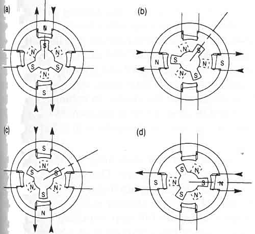 above (Diagram 2): Movement of a stepper motor rotor as current is pulsed to the stator. |
Changing the current flow to the next stator winding, the magnetic field will be changed 90°. The rotor will only move 30° before its magnetic fields will again align with the change in the stator field. The magnetic field in the stator is continually changed as the rotor moves through the 12 steps to move a total of 360°. Diagram 2 (left) illustrates the position of the rotor changing as the current supplied to the stator changes.
In Diagram 2a (left) one can notice that when current is applied to the top and bottom stator windings, they will become magnetized with the top part of the winding being the north pole, and the bottom part of the winding being the south pole. Note that this will cause the rotor to move a small amount so that one of its south poles is aligned with the north stator pole (at the top), and the opposite end of the rotor pole, which is the north pole, will align with the south pole of the stator (at the bottom). A line is placed on the south-pole piece that's located at the 12 o'clock position in Diagram 2a so that one can follow its movement as current is moved from one stator winding to the next. In Diagram 2b current has been turned off to the top and bottom windings, and current is now applied to the stator windings shown at the right and left sides of the motor. When this happens, the stator winding at the 3 o'clock position will have the polarity for the south pole of the stator magnet, and the winding at the 9 o'clock position will have the north-pole polarity. In this condition, the next rotor pole that will be able to align with the stator magnets is the next pole in the clockwise position to the previous pole, meaning that the rotor will only need to rotate 30° in the clockwise position for this set of poles to align itself so that it attracts the stator poles. In Diagram 2c notice that the top and bottom stator windings are again energized, but this time the top winding is the south pole of the magnetic field and the bottom winding is the north pole. This change in magnetic field will cause the rotor to again move 30° in the clockwise position until its poles will align with the top and bottom stator poles. One can see that the original rotor pole that was at the 12 o'clock position when the motor first started has now moved three steps in the clockwise position. In Diagram 2d one can notice that the two side stator windings are again energized, but this time the winding at the 3 o'clock position is the north pole. This change in polarity will cause the rotor to move another 30° in the clockwise direction. Note that the rotor has moved four steps of 30° each, which means the rotor has moved a total of 120° from its original position. This may be verified by the position of the rotor pole that has the line on it, which is now pointing at the stator winding that's located in the 3 o'clock position.
|
HOME | PREVIOUS: Stepper Motors: Types | NEXT: Switching Sequence for Full and Half-Step Motors