 A
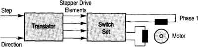
stepper motor system is comprised of a translator circuit that receives
a signal that includes the number of steps and the direction. The translator
circuit sends four individual control signals to the switch set circuit and the switch set circuit sends power signals to each of the two phases
(windings) in the stepper motor. The figure on the left shows a typical
stepper motor system. Note that the signal for the number of steps is
included with this diagram -- it's a series of square-wave pulses (one
for each step the rotor should move). The signal for the direction is
a constant-voltage signal that's either positive or negative.
A
stepper motor system is comprised of a translator circuit that receives
a signal that includes the number of steps and the direction. The translator
circuit sends four individual control signals to the switch set circuit and the switch set circuit sends power signals to each of the two phases
(windings) in the stepper motor. The figure on the left shows a typical
stepper motor system. Note that the signal for the number of steps is
included with this diagram -- it's a series of square-wave pulses (one
for each step the rotor should move). The signal for the direction is
a constant-voltage signal that's either positive or negative.
The translator normally receives its signal from a programmable logic controller (PLC) or other type of microprocessor controller. In some cases, the controller is specifically designed to provide motion control or sequential control. The controller sends a command signal that consists of the number of steps the rotor should turn, and the direction signal indicates the direction. The step signals can be detected with LEDs or with an oscilloscope as they are sent to the translator. When troubleshooting the translator, one may want to know if it's receiving the pulses that represent the steps. An LED indicator or scope may be used to see these pulses. The direction of rotation signal can be detected with a voltmeter to determine if the signal is a positive voltage or negative voltage.
Unipolar Drive Amplifier
The simplest type of drive amplifier for a stepper motor is the unipolar drive. From the electrical diagram in the figure below note that the circuit consists of two transistors that are connected to each winding set (phase). Also note that the two windings comprising each set have a terminal connection at the point where the two windings are connected. The positive voltage supply is connected at this point. Each winding has a transistor emitter-collector circuit connected in series with it, and the negative terminal of the voltage supply is connected to the emitter of each transistor.
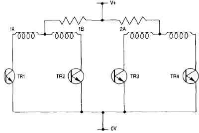
This type of amplifier is called a unipolar drive because current can only flow in one direction at any one time. The motor must be a bipolar type so that current can be reversed in the second segment of the winding to get the motor to run in the reverse direction.
Chopper Drive Amplifier
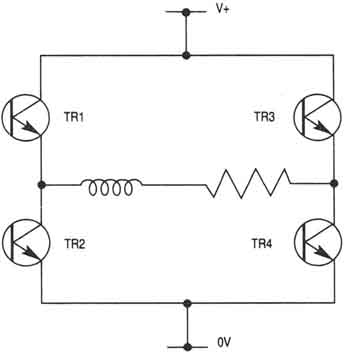 FIGURE 1: A chopper amplifier circuit for a stepper motor. This circuit is also known as a re-circulating chopper amplifier. |
The chopper drive amplifier permits a way to control the current in the stepper windings to provide better torque control. Ill. 1 (left) shows a schematic diagram of this type of drive amplifier. Notice that each winding segment has four transistors connected to it. The transistors are identified as TR1 through TR4. The circuit also has two diodes and small resistor (approx. 0.1 Ω). Current is supplied to the winding by energizing TR1 and TR4, or by energizing TR2 and TR3. The direction of current flow will determine the polarity of the stator pole. In the chopper circuit the combination of transistors permits the
current to be re-circulated through the winding if the current requirement
to provide the motor torque at any instant is reached. Hence, no
current is wasted -- allowing the drive amplifier and motor to operate
more efficiently. In common resistance-limited (R-L) drives, the
motor draws maximum current when the rotor is not turning -- this
results in wasting up to 90% of current to the motor. In the chopper
amplifier the chopper circuit allows the transistors to chop the
current so that it can control the re-circulation through the windings
so that little current is wasted. |
Chopper Drive Amplifier and Power-Dumping Control
Permanent magnet motors generate a current anytime the rotor is turning -- this is a troublesome issue. This generated current may cause a problem when the motor starts to decelerate and the current will become stronger than the supplied current. If this happens, the excess current may damage the switching circuit components.
A way to solve this problem is by including a power-dumping circuit with the switching transistors. Ill. 2 (below) shows an example of the location of the power dump circuit. In this diagram the power-dump circuit is shown as a block.
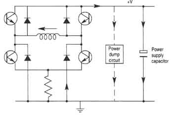
FIGURE 2: A dump circuit is shown connected across the +V and ground in parallel with the power supply capacitor. This circuit re-circulates excess current generated during motor deceleration. This lets the stepper motor operate more efficiently.
Ill. 3 (below) shows the detailed electronic schematic for the power-dump circuit. This circuit has a detector which checks the current threshold and turns off all transistors if the threshold is exceeded. When all transistors are off, current will be isolated from the circuit components, and a capacitor will permit a path for the current to circulate through the winding until it dissipates below the threshold and becomes harmless. This circuit topology also allows a means to slightly increase the efficiency of the drive since the excess current built up during deceleration is regenerated instead of wasted.
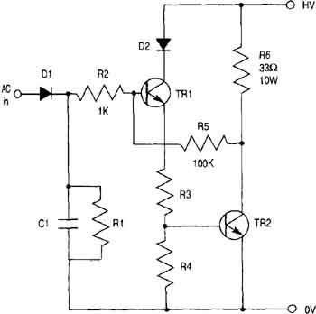
FIGURE 3: Detailed electrical diagram of the dumping circuit
for the stepper motor chopper amplifier shown in Figure 2.
The components making up a power-dump circuit use the rectifier and capacitors to establish a reference voltage from the AC applied voltage. The AC applied voltage is separate from the dc voltage the circuit will see from the motor windings. When the motor decelerates, the voltage that's generated by the stepper motor rotor will exceed the reference voltage, which will turn on transistor TR2. When TR2 is turned on, it will provide a path between the two potentials (HV and 0V) through the 33 Ω resistor. This path allows the excess current to be regenerated, which will cause it to dissipate. When the current has dissipated below the threshold, the transistor is turned off again and the circuit is waiting for the threshold to be exceeded again.
HOME | PREVIOUS: Microstep Mode | NEXT: Stepper Motor Applications