AMAZON multi-meters discounts AMAZON oscilloscope discounts
The drive in the diagram below has two types of on/off outputs available -- they are shown on the right side of the diagram. A set of NO (normally open) contacts is provided at terminals TB2-9 and TB2-10. These contacts are controlled by the drive and their function can be selected in the drive parameters. For example, these contacts can be selected to close when the drive is enabled, or they can be used to indicate the drive in a fault condition. A solid-state output is available at terminals TB2-19 and TB2-20. This circuit is basically the emitter and collector of a transistor. When the drive controls this circuit, it sends a signal to the transistor base, which in turn causes the collector-emitter circuit to go to saturation.
Another output that's available from the AC drive is a frequency signal that can be sent to a frequency meter. The frequency meter can be located on the operator panel where it will be used to indicate the speed signal that the drive is sending to the motor.
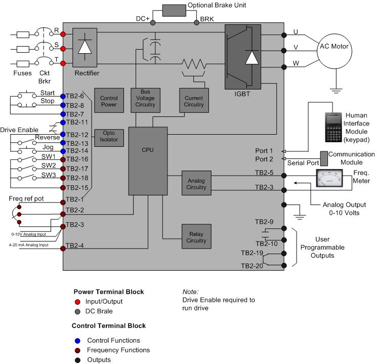
above: A block diagram of a variable-frequency drive that also shows the components that are connected to the drive to provide additional control. Adapted from an Allen-Bradley/Rockell Automation AC drive schematic.