AMAZON multi-meters discounts AMAZON oscilloscope discounts
The block diagram of a typical variable-frequency drive can be divided into three major sections:
- the power-conversion section
- the microprocessor control section (CPU) and the control section that includes the external switches an signals to control the drive operations
- the power section where AC voltage is converted to DC and then DC is inverted back to 3-phase AC voltage
The block diagram below contains the power section of the VFD as three separate sections to indicate the three main functions:
- the rectifier
- the filter
- the switching section that uses regular transistors, darlington pair transistors, or insulated gate bipolar transistors (IGBT) to invert the DC voltage back to AC voltage with the proper frequency.
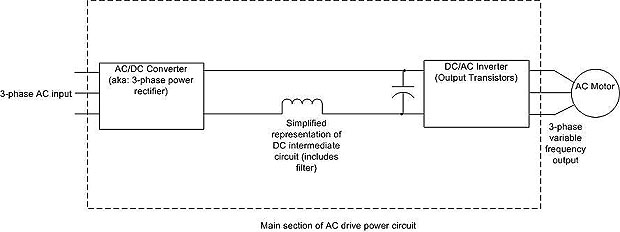
above: The VFD shown as three separate sections: rectifier (where AC is converted to DC); the DC intermediate circuit which contains the capacitor and inductor for filtering. The third section is the DC-to-AC inverter where DC is turned back to three-phase AC.