AMAZON multi-meters discounts AMAZON oscilloscope discounts
In motor control circuits, the components are broken into two groups: the control components, which are the switches and coils that control the load, and the load components such as motors that cause the system to perform some type of action. The part of the circuit that has the controls is called the control circuit, and the part of the circuit that has the motor init's called the load circuit. Typically the switches and wires in the control circuit use lower voltages than the load and smaller currents than the load. In fact in most circuits, the load will be a single-phase or three-phase motor.
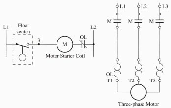
Figure 1 shows a ladder diagram of a control circuit and a load circuit. Notice in this figure that the control circuit is shown on the left, and it has a float switch connected to the relay coil. An NC set of overload (OL) contacts is shown connected in series with the motor starter coil. The load circuit is shown on the right side of the figure and one can see that it consists of a three-phase motor starter and a three-phase motor. It's important to note that the relay coil is technically a load, but it's considered part of the control circuit because of the function it performs.

Above: Fig. 1: A ladder diagram of a control circuit and a load circuit.
Float switch, Motor Starter Coil, Three-phase Motor.
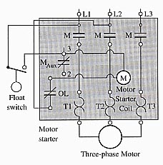
The same control and load circuits are shown as a wiring diagram in Figure 2. When this circuit is shown as a wiring diagram, you will notice that some of the control circuit components such as the motor starter coil are drawn where they are physically located on the motor starter. Since the motor starter contacts are part of the load circuit, it's hard to determine in a wiring diagram what components are part of the load circuit and what components are part of the control circuit. In some diagrams the load circuit is usually drawn with darker and wider lines than the wires of the control circuit to indicate the wires are larger. The remaining part of this section will explain the different types of control circuit configurations and load circuit configurations.

Above: Fig. 2: An example of a wiring diagram that shows a control
circuit and a three-phase motor in the load circuit. Notice the motor
starter is shaded in the wiring diagram so that you can locate it and all of its terminals.

