AMAZON multi-meters discounts AMAZON oscilloscope discounts
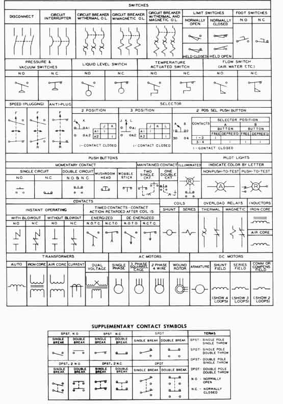
Other pilot devices such as pressure switches, flow switches, float switches, temperature-activated switches, and time-delay relays and lamps are also used in motor control circuits (see Figure 1). These symbols are standard for pilot devices used in motor control circuits. When one encounters a typical motor control diagram on a blueprint, one can use the symbols in this figure to identify each type of switch. Notice that the symbol for the part that causes the switch to activate is shown at the bottom of each symbol. For example, the symbol for a liquid-level switch is a circle, which represents the ball float typically found on this type of switch and the symbol for the pressure switch looks like the pressure dome. The symbol for each switch should look similar to the actuator for that switch. Also notice that the contact arm for each switch will be shown in the NO or NC position.

Above: Fig. 1 (click here or image to enlarge).
Electrical symbols for pilot devices and other motor control devices. STANDARD
ELEMENTARY DIAGRAM SYMBOLS. The diagram symbols shown below have been adopted
by the Square D Company and conform where applicable to standards established
by the National Electrical Manufacturers Association (NEMA).
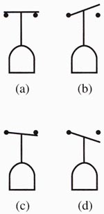
While examining each symbol carefully, notice whether its contacts are NO or NC. Understand that the switch arm can be drawn on top of or below the terminals. Each of these conditions allows four combinations of switches to be identified. It's important to understand these subtle differences. For instance, Figure 2 shows a pressure switch drawn with its contact arm in each of the four ways described previously, so each switch is different from the other. Figure 2a shows the switch arm NC above the contact terminal and the switch is activated by pressure. This indicates that the switch is an NC switch, and an increase in pressure will cause the switch to open. It may help to remember the switch symbol by the type of application the switch would be used for. For example, this type of switch would be used as a high-pressure safety switch. When the pressure gets too large in a system, the switch opens and shuts off a compressor that is adding pressure to the system. The pressure switch in Figure 2b shows an NO switch with the switch arm above the contact terminal. This type of switch will activate a circuit when pressure falls. An application for this type of switch is to be used to turn on a compressor when air pressure drops below a minimum, so the system will sustain the pressure. Since the switch arm is drawn above both of these switches, they may also be called high-pressure switches.

Above: Fig. 2 (a) NC pressure switch. (This switch
may be referred to as an NC high-pressure switch.) (b) NO pressure switch.
(This switch may also be referred to as an NO high-pressure switch.) (c)
NC pressure switch. (This switch may be referred to as an NC low-pressure
switch.) (d) NO pressure switch. (This switch may be referred to as an
NO low-pressure switch.)
Figure 2c shows an NC pressure switch with the switch arm below the contact terminal. This symbol indicates that when pressure decreases, the switch contacts will fall to the open position. This type of switch can be used as a low-pressure safety switch. For example, if a system is to maintain a minimum oil pressure, the switch will open if the oil pressure drops below the setpoint. Figure 2d shows an NO pressure switch with the switch arm below the contact terminal. When pres sure increases, it will cause the switch arm to go up and close. This type of switch can be used to start a motor when the pressure gets too high. Since the switch arm is shown below the contact on both of these switches, they may be referred to as low-pressure switches.
It's important to remember that the pressure switches are only sold with NO or NC contacts or the combination of one set of NO and one set of NC contacts. Again, like the limit switches, the conditions the switches are used in when they are mounted on machinery may refer to the function of the switch in the name the machine manufacturer gives the switch. For example, the switch may be called the compressor high-pressure cutout safety, or it may be called the low oil pressure protection switch. In both of these cases the switch is still a pressure switch and a set of NO or NC contacts is used to control circuit current when pressure increases or decreases.
Whichever way the contact arm is drawn, a decrease in the physical parameter the switch is measuring will cause the switch arm to drop, and an increase will cause the arm to raise. The next section will show how all of the pilot devices are used together to make common motor control circuits.

