AMAZON multi-meters discounts AMAZON oscilloscope discounts
9.1 SPEED-TORQUE CURVE
A typical computerized test station consists of a power analyzer, dynamometer controller, digital indicator, and multimeter (see Figs.9.1 and 9.2).This kind of test station will quickly generate speed-torque curves and summary sheets, as shown in ill. 9.3, or full sets of curves for speed versus torque, efficiency, current, watts, and power factor, as shown in ill.9.4.Different inertial compensations can easily result in an entire family of curves and can greatly affect results. By using a dynamometer controller to take the motor from idle to a predetermined minimum speed and back to idle at a controlled rate, inertial effects will nearly disappear simply by interpolating for the same speed points and averaging the two sets of data. Points from the resulting curves will then compare very well with static measurements made at the same performance point. Finally, an accurate stall point should consist of an average of at least three sets of locked rotor data at different rotor positions.
In order to obtain accurate test results, the maximum motor torque should equal at least 30 percent of the dynamometer rating. Voltage drops during the test will drastically affect results and require heavier wiring than specified by the National Electrical Code. A good rule of thumb would increase wiring in conduit by six wire gauges and bench wiring by four wire gauges. Voltage control devices such as power stats must also minimize voltage drops, either by voltage regulation or by selecting a rating of at least four times the maximum motor current. The power supply frequency shouldn't vary more than 0.5 percent from the rated value. In addition, polyphase systems shouldn't exceed 0.5 percent voltage unbalance between phases.
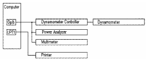
Figr. 9.1 Typical motor test bench diagram.
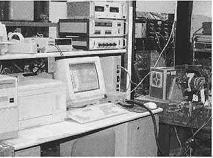
Figr. 9.2 Typical test station.
9.1.1 Acceleration Test
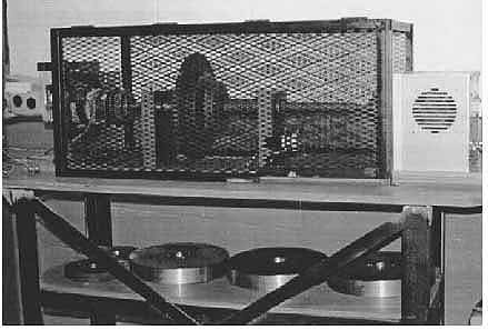
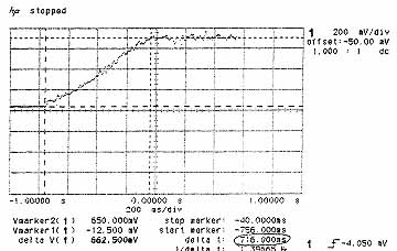
This test determines the acceleration characteristics of a motor for a given amount of inertia and load torque. The inertia test stand shown in ill.9.5 includes a set of inertia wheels that will provide a range of inertias from 50 to 4000 lb -in^2 in 50-lb -in^2 increments and an analog tachometer to monitor speed. In order to minimize oscillations, the setup uses low-backlash couplings between the motor, the inertia wheel shaft, and the dynamometer. An oscilloscope monitors the voltage from the analog tachometer and provides voltage and time data to a PC through the general-purpose interface bus (GPIB) connection. At this point, the PC calculates the speeds based on the tachometer voltage constant and plots the acceleration curve (see ill.9.6).
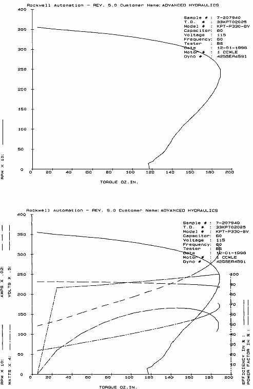
Figr. 9.3 Speed-torque curve and summary sheet generated by a computerized
test station. (bottom) Figr. 9.4 Speed-torque, efficiency, current,
watts, and power factor curves generated by a computerized test station.
AC motors and open-loop dc motors could use the bench shown in ill. 9.1 to acquire and document additional data such as torque, efficiency, current, and watts. However, closed-loop motors require a different approach, as outlined in the dc motor test section on speed profiles.
9.1.2 Good Test Practices
1. Review test requirements for consistency with UL and other requirements to avoid wasted test time. Obtain clarification as needed.
2. Measure the resistance of the motor windings using a precision multimeter or bridge and record ambient temperature. Ensure that resistance meets winding specifications prior to any tests.
3. Perform high-potential tests per UL requirements prior to energizing the motor. In the absence of other information, a good rule of thumb would apply a voltage equal to (1000 plus twice the rated voltage) times 1.2 for at least 1s.
4. Select stable capacitors within at least 1 percent of specified values and check for drift rather than relying on old measurements marked on the capacitor. Always discharge the capacitors prior to checking the value to avoid damage to the meter. Switch between all selections on capacitor decade boxes when bleeding charge.
5. Confirm that the dynamometer has appropriate cooling operating.
6. Use brass-tipped setscrews in the coupling and check tightness periodically to avoid bad data.
7. Select appropriate ranges for equipment that does not auto-range.
8. Minimize coupling backlash and torsional deflection.
9. Monitor display to confirm at least the initial printout.
10. If the motor has a ground wire, connect it to the workstation ground. 11. Recheck motor connections against specifications prior to test.
12. Adjust speed-torque test time and minimum speed to minimize motor oscillation below breakdown.
