AMAZON multi-meters discounts AMAZON oscilloscope discounts
There are many residential, commercial, and industrial customers of electrical power systems in the United States today. To meet this vast demand for electrical power, power companies work in combination to produce tremendous quantities of electrical power. This vast quantity of electrical power is supplied by power generating plants. Individual generating units that supply over 1000 megawatts of electrical power are now in operation at some power plants.
Electrical power can be produced in many ways, such as from chemical reactions, heat, light, or mechanical energy. The great majority of our electrical power is produced by power plants located throughout our country, which convert the energy produced by burning coal, oil, or natural gas, by falling water, or by nuclear reactions into electrical energy. Electrical generators at these power plants are driven by steam or gas turbines, or by hydraulic turbines in the case of hydroelectrical plants. This Section will investigate the types of power systems that produce the great majority of the electrical power used today.
Various other methods, some of which are in the experimental stages, may become future power production methods. These include solar cells, geothermal systems, wind-powered systems, magnetohydrodynamic (MHD) systems, nuclear fusion systems, and fuel cells. These alternative power systems will be discussed in greater detail in Section 5.
TERMINOLOGY
This Section deals with modern electrical power production systems. After studying this Section, you should have an understanding of the following terms:
- Fossil Fuel System
- Electrical Power Plant
- Steam Turbine
- Load Factor (Demand)
- Capacity Factor
- Boiler
- Superheater
- Desuperheater
- Feedwater
- Reaction Turbine
- Economizer
- Feedwater Heater
- Condenser
- Feedwater Purifier
- Coal Pulverizer
- Hydroelectric System
- Hydraulic Turbine
- Pumped Storage Hydroelectric System
- Nuclear Fission System
- Nuclear Reactor
- Moderator
- Boiling-Water Reactor (BWR)
- Pressurized-Water Reactor (PWR)
ELECTRICAL POWER PLANTS
Most electrical power in the United States is produced at power plants that are either fossil fuel steam plants, nuclear fission steam plants, or hydroelectric plants. Fossil fuel and nuclear fission plants utilize steam turbines to deliver the mechanical energy needed to rotate the large three phase alternators that produce massive quantities of electrical power. Hydroelectric plants ordinarily use vertically mounted hydraulic turbines.
These units convert the force of flowing water into mechanical energy to rotate three-phase alternators.
The power plants may be located near the energy sources, near cities, or near the large industries where great amounts of electrical power are consumed. The generating capacity of power plants in the United States is greater than the combined capacity of the next four leading countries of the world. Thus, we can see how dependent we are upon the efficient production of electrical power.
Supply and Demand
The supply and demand situation for electrical energy is much different from that of other products that are produced by an organization and later sold to consumers. Electrical energy must be supplied at the same time that it is demanded by consumers. There is no simple storage system that may be used to supply additional electrical energy at peak demand times. This situation is unique, and it necessitates the production of sufficient quantities of electrical energy to meet the demand of the consumers at any time. Accurate forecasting of load requirements at various given times must be maintained by utility companies in order that they may recommend the necessary power plant output for a particular time of the year, week, or day.
Plant Load and Capacity Factors
There is a significant variation in the load requirements that must be met at different times. Thus, the power plant generating capacity utilization is subject to continual change. For this reason, much of the generating capacity of a power plant may be idle during low demand times. This means that not all the generators at the plant will be in operation.
There are two mathematical ratios with which power plants are concerned. These ratios are called load factor (demand factor) and capacity factor. They are expressed as:
Load (demand) factor = Average load for a time period/ Peak load for a time period
Sample Problem:
Given: a power plant has an average load of 220 MW and a peak load of 295 MW over a 24-hour period.
Find: the load factor of the power plant during the 24 hour period.
Solution:
Load factor = Average Load / Peak Load
= 220 MW / 295 MW
Load factor = 0.745
Capacity factor = Average load for a time period / Output capacity of a power plant
Sample Problem:
Given: a power plant has an average load of 112 MW and an output capacity of 166 MW.
Find: the capacity factor of the power plant.
Solution:
Capacity factor = Average Load / Capacity
= 112MW / 166 MW
Capacity factor = 0.675
It would be ideal, in terms of energy conservation, to keep these ratios as close to unity as possible.
FOSSIL FUEL SYSTEMS
Millions of years ago, large deposits of organic materials were formed under the surface of the earth. These deposits, which furnish our coal, oil, and natural gas, are known as fossil fuels. Of these, the most abundant fossil fuel is coal, and coal-fired electrical power systems produce about one-half of the electrical power used in the United States. Natural-gas-fired systems are used for about one-fourth of our electrical power, while oil-fired systems produce around one-tenth of the power at the present time. The relative contributions of all of these systems to the total electrical power produced in the United States are subject to change, as the result of the addition of new power generation facilities and fuel availability. At the present time, over 80 percent of our electrical energy is produced by fossil fuel systems. It is important to note that these percentages vary from year to year.
A basic fossil fuel power system is shown in FIG. 1. In this type of system, a fossil fuel (coal, oil, or gas) is burned to produce heat energy. The heat from the combustion process is concentrated within a boiler where circulating water is converted to steam. The high-pressure steam is used to rotate a turbine. The turbine shaft is connected directly to the electrical generator and provides the necessary mechanical energy to rotate the generator.
The generator then converts the mechanical energy into electrical energy.
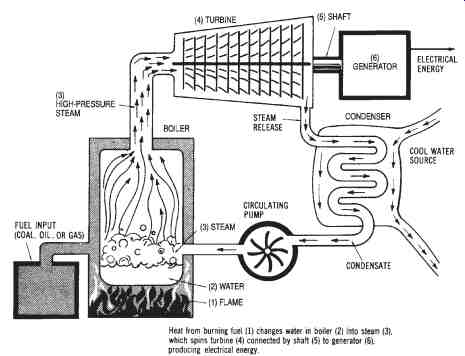
FIG. 1. A basic fossil fuel power system
Fossil Fuels
Fossil fuels are used to supply heat, by means of chemical reactions, for many different purposes. Such fuels contain carbon materials that are burned as a result of their reaction with oxygen. These fossil fuels are used as a direct source of heat when burned in a furnace, and are used as a heat source for steam production when used in a power plant boiler system.
The steam that is generated is used for rotating the steam turbines in the power plants.
Fossil fuels vary according to (1) their natural state (solid, liquid, or gas), (2) their ability to produce heat, and (3) the type of flame or heat that they produce. Coal and coke are solid fossil fuels, and coal is used extensively for producing heat to support electrical power production. Oil, gasoline, and diesel fuel, which are liquid fossil fuels derived by petroleum processing, are used mostly in conjunction with internal combustion engines. However, oil is used as a heat source for many power plants. Natural gas is the primary gaseous fuel used for electrical power production.
Coal-fired Systems
The use of coal as a fuel to supply the necessary heat energy at a power plant requires the use of specialized stokers or grating units. These units reduce the size of the lump coal. Most of these units are mechanical systems that agitate the coal to reduce it into smaller lumps. The coal used at a power plant usually is sent through a stoker or grating unit by conveyer belts. A large gravity-feed hopper is often used to route very small lumps of coal into a pulverizing unit.
The pulverizer looks very similar in construction to a large ball-bearing unit. The coal is routed into the pulverizer unit, where large, rotating steel balls crush the coal until it is in particles about the same size and consistency as face powder. These fine particles are routed into the furnace by air pressure produced by force-draft fans. The coal is held in suspension until it is ignited. It then releases a large amount of heat energy. The suspended powder-fine coal particles allow sustained combustion to take place in the furnace. The pulverized coal speeds up the combustion process.
Coal-fired Plant Operation
Since the majority of electrical power produced today is from coal-fired systems, we will discuss the basic operation of this type of system. In a steam plant that produces electrical power, most of the operations are used for rotating the steam turbine. Remember that in any steam plant, heat must be produced. This heat produces steam, which moves the steam turbine, which produces a rotary motion, which finally produces electrical power.
FIG. 2 shows the layout of a typical coal-fired electrical power plant. Notice that it is located near a river, so that cooling water can be easily pro vided. The water is also used to produce steam to operate the steam turbine that rotates the generator unit. A cross-section of a coal-fired power plant is shown in FIG. 3.
The maximum efficiency of the coal-fired plant of today is approximately 40 percent when using a powdered-coal spraying process. Efficiency is calculated as:
Efficiency = Power Output / Power Input
where power output is electrical power produced.
Coal requires extensive handling equipment. The coal itself must be handled, and then the ash and dust particles must be removed. At the power plant, the coal is moved to overhead hoppers by means of conveyor belts. These hoppers may typically be as large as eight stories high. The coal usually is fed into pulverizing mills by means of gravity. It is ground to a consistency similar to that of face powder, using the method discussed previously. The powdered coal is then dried using plant exhaust gases, and then blown into a furnace. The coal is ordinarily blown through a tangential or "T" burner into the furnace. These burners are placed in the four corners of a square furnace to create the turbulence needed for complete combustion.
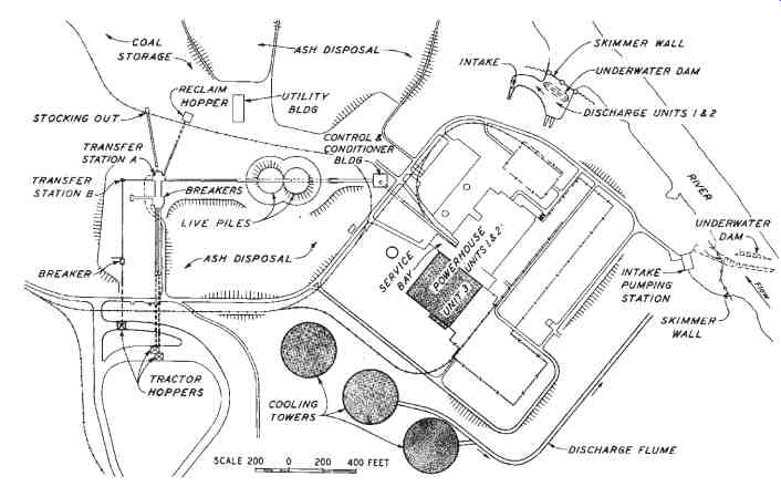
FIG. 2. Layout of a typical coal-fired electrical power plant.
( Tennessee Valley Authority)
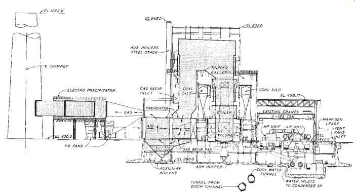
FIG. 3. Cross-section view of a typical coal-fired power plant.
( Tennessee Valley Authority)
Another method of firing the furnace is the fluidized bed. Advantages of the fluidized bed are that it produces less pollution and can burn a lower quality coal. In a fluidized bed, coal is crushed to form 1/8-inch to 1/4-inch diameter particles. When air is blown through a layer of this coal, the particles will float on a cushion of air. The pressure has to be adjusted very accurately, so that the particles are fluidized without being blown away from the bed. The fluidized bed is the basis of a direct-combustion process. If the bed is hot enough, the flow of air through the bed leads to almost total combustion, and can provide a greater efficiency with less ash and dust.
Power plant boilers, such as the one shown in FIG. 4 incorporate several special units to improve their thermal efficiency and economy of operation. An economizer is placed at the exhaust exit to preheat the water coming into the boiler. The economizer also preheats the air blowing into the furnace. A superheater is a bank of tubes located at the hottest spot of the furnace. These tubes take up the steam after it leaves the boiler and before it enters the turbine. The purpose of the superheater is to raise the tempera ture of the steam. Increased superheat decreases the percent of water per unit volume in the steam, which increases turbine life. A desuperheater is the next part of the system. The desuperheater brings the steam down to a temperature at which it can be condensed. The feedwater in a power plant is used over and over, with water added only to account for losses. The feed water must be very pure to ensure long life of the boiler tubes. Some common power plant terminology is summarized in TABLE 1.
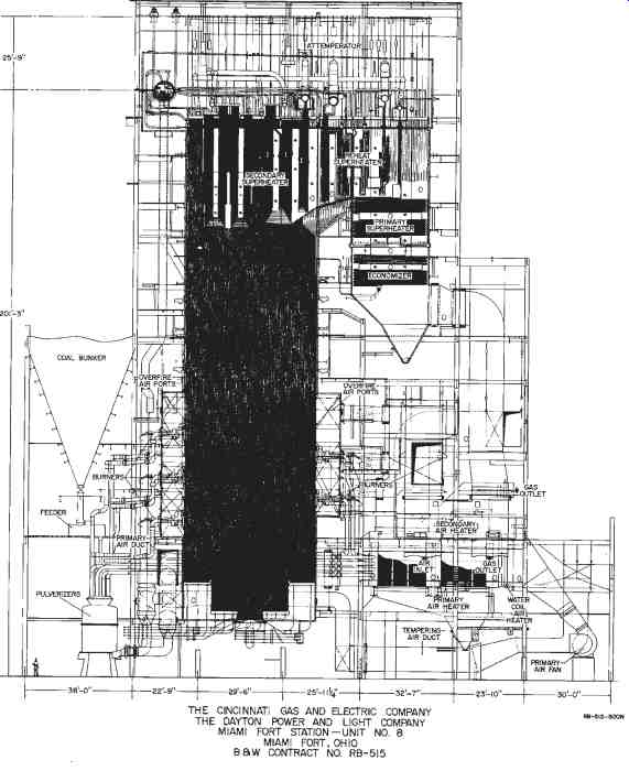
FIG. 4. Natural circulation radiant boiler used by the Cincinnati
Gas and Electric Company (Babcock and Wilcox)
====
TABLE 1. Power Plant Terminology
|
|
After steam has been produced, a rotary motion must be developed.
This rotary motion is produced by a steam turbine. A steam turbine, shown in FIG. 5 is typically made up of as many as 1500 blades. The rotor is usually divided into two parts-the high pressure rotor and the low pressure rotor. The low-pressure rotor is larger in diameter than the high-pressure rotor. Steam is channeled to the high-pressure rotor, and it is then routed to the low-pressure rotor.
Steam turbines ordinarily achieve a maximum efficiency of less than 30 percent, but only when run at very high speeds. Some turbines can pro duce as much as 160,000 horsepower. A speed of 3600 rpm is needed to develop a 60-Hz electrical power output. The standard power frequency in the U.S. is 60-Hz. Large three-phase AC generators are connected to DC exciters. Generators are often cooled with hydrogen because hydrogen has less than one-tenth the density of water. Therefore, much less energy is required to recirculate the hydrogen for cooling purposes.
The process just described summarizes the operation of a steam power plant. There are several variations to the basic process; however, most plants use similar methods. The individual parts of a steam-generating system will be discussed in more detail in the following sections.
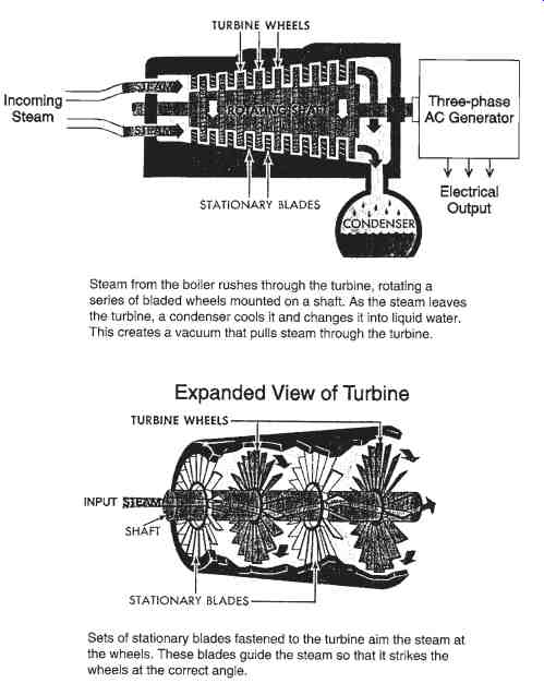
FIG. 5. Steam turbine principle of operation
STEAM TURBINES
Steam turbine systems are now used to produce over 80 percent of the electrical power used in the United States. The force of steam produces a rotary motion (mechanical energy) in a steam turbine. This mechanical energy is converted to electrical energy by three-phase generators connected by a common shaft. Both fossil fuel systems and nuclear fission systems utilize steam turbines as prime movers (rotary motion producers).
A reaction turbine channels high-velocity steam through a set of blades mounted on a rotary shaft. The reaction turbine usually has more than one set of blades, with each set having a different diameter. As the steam passes though the first section of blades, its pressure is reduced, and its volume is increased. Due to the increased volume, the additional sections of blades must have larger diameters and longer sets of blades.
These combined sections of blades direct the high-velocity steam in such a way that a maximum rotational force is produced by the turbine.
The design of a steam turbine is very critical for the efficient production of electrical power. Several characteristics of steam turbines cause de sign problems. Steam turbines must be operated at high rotational speeds, so the blades must be designed to withstand a tremendous amount of centrifugal force. The rotor and blade assemblies for steam turbines are usually machined from a forged piece of chromium and steel alloy. This assembly must be very precisely balanced before the machine is put into operation. The leakage of steam from the enclosed rotor and blade assembly must be prevented. Solid seals cannot be used along the rotor shaft, so so-called "steam" seals are used to provide a minimum clearance between the seals and the shaft. The bearings of a steam turbine must be carefully designed to withstand both axial and end pressures of high magnitudes.
Steam turbines used in electrical power production must be rotated at a constant speed. If turbine speed changes, the frequency of the genera tor output voltage will be changed from the standard 60-Hz value. There fore, a system of governors is used in a steam turbine to regulate its speed.
The governor system adjusts the turbine speed by compensating for changes in generator power demand. As more load is placed on the generator (increased consumption of electrical power), the generator offers an in creased resistance to rotation. Thus, power input to the turbine must be in creased accordingly. The governor system of the turbine automatically adjusts the steam input to the turbine blades to compensate for increases and decreases in the load demand placed upon the generator that it drives.
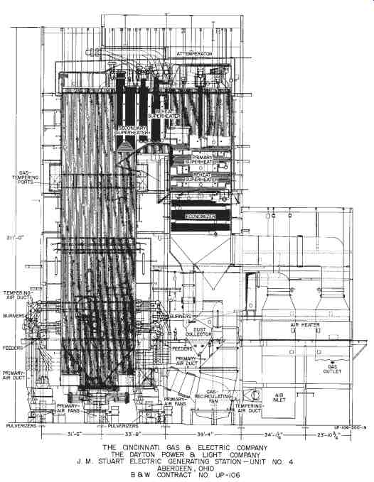
FIG. 6. Once-through universal boiler used by the Cincinnati
Gas and Electric Company (Babcock and Wilcox)
BOILERS
Boilers (see FIGs. 4 and 6) are an important part of steam power production systems. The function of a boiler is to provide an enclosure in which pressurized water can be heated to a high temperature to produce steam. The heat from burning fossil or nuclear fuels is transferred to an area through which pressurized water flows, and the water is converted to steam through this procedure.
The transfer of heat within a boiler utilizes the three methods of heat transfer: radiation, convection, and conduction. The radiation method involves the movement of heat energy from a warm area to a cool area, and is dependent upon temperature difference and the ability of materials to absorb heat. The conduction method requires contact between the heat source and the heated area, and it relies upon the heat conductivity of the heated material. Convection is the movement of heat from a hot area to a cooler area by means of an intermediate substance, such as gas. Each of these three methods of heat transfer occurs in varying amounts, depending upon boiler design.
A boiler that functions properly is a very critical part of the power production system, as the boiler operation determines the quantity of steam available to produce the rotary motion of the turbine. When more power input for the generating process is required because of an increased load on the system, the boiler must deliver more steam to the turbine.
Boilers must be able to provide effective water circulation, efficient fuel combustion, and maximum heat transfer to the circulating water. The boilers used in most steam power plants today are called water-tube boilers.
Their design consists of banks of tubes, separated by heat insulation; water is circulated through the tubes under high temperature and high pres sure. Boiler design is very important for an efficient steam power plant operation.
Boiler Auxiliary Systems
There are several auxiliary systems used in a steam power plant to increase the operation and efficiency of the boilers. Some of these systems were mentioned briefly in previous sections. One auxiliary system is called an economizer. Economizers utilize the hot exhaust gases from the fuel reactions within a boiler to preheat the cold feedwater that is pumped into the boiler. Thus, the economizer uses the waste gases, which would otherwise be emitted through the exhaust stack, for an important purpose.
This improves the efficiency of the power plant.
In addition to the economizer, feedwater heaters and preheaters are used to increase the water temperature before its entry into the boiler. These systems heat the pumped feedwater by means of steam, which is circulated through the unit. In some plants, systems called superheaters are used.
These units consist of banks of tubes located at the hottest area of the boiler. Steam flows through these tubes before its entry into the steam turbine.
The purpose of the superheater is to cause the steam to reach a higher temperature so as to produce more energy in the steam turbine. Each of these auxiliary systems helps to improve the efficiency of steam power plants.
Condensers and Purifiers
The condensers and feedwater purifiers used at steam power plants are also important in the production of energy. Condensers are used to cool the used steam that has passed through the steam turbine. The condensed water is continuously recirculated through the system. Feedwater purifiers are used to clean the impurities from the feedwater, which is obtained from a water source located adjacent to the power plant. The feed water purifiers play an important part in power plant operation. Without them, the metal used in the construction of the boiler would corrode, producing a slag build-up on the boiler walls, which eventually would destroy the boiler. Also, impurities in the steam can cause damage to the precision blades used in the steam turbines. In addition, the gases that are contained in the feed water must also be removed. These gases are removed by a unit called a deaerator.
The quantity of feedwater that reaches the steam turbine in the form of steam is dependent on the amount of evaporation that takes place in the system. In the power plant, a comparative analysis must be made of the quantity of water entering the boiler and the quantity of steam coming out of the steam turbine. Adjustments in feedwater flow are based on this comparison.
Future of Coal-fired Power Systems
Pulverized-coal systems have been used for many years to produce energy for conversion to electrical power. However, there are now more environmental restrictions on these systems. Major problems include sulfur dioxide and nitrogen oxide emission controls for the power plants, particularly sulfur-dioxide controls. More stringent environmental controls in crease the capital cost of power system operations. Even though coal is the most abundant fossil fuel, it is also the dirtiest in terms of environmental factors. Thus, a significant problem of electrical power technology is how to utilize coal in an environmentally acceptable way.
Electrical power systems are the largest consumers of coal in the United States. With a decrease in the availability of oil and natural gas, coal must again be relied upon as the prime electrical power source of the future. Power production systems must be designed that will produce electrical energy in the most economical and environmentally responsible way.
Coal-fired System Simulator
A coal-fired electrical power system simulator can't be used to study this method of power production. The various subsystems of the coal-fired power plant are interconnected within the overall system. There are basically five subsystems for this type of power plant. These subsystems are the feedwater system, the fuel and air system, the coal-pulverizing system, the boiler-water system, and the steam and turbine system. Each of these five sub systems is shown in the diagrams of FIGs. 7 through 11.
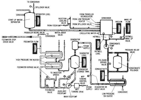
FIG. 7. The feedwater subsystem (Omnidata, Inc.)
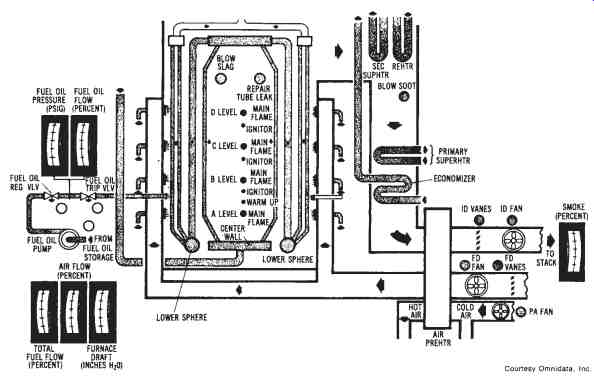
FIG. 8. The fuel and air subsystem (Omnidata, Inc.)
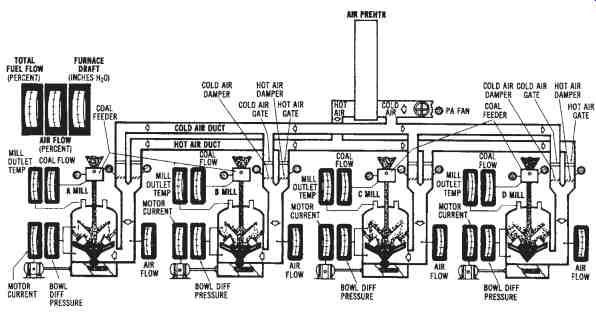
FIG. 9. The coal pulverizer subsystem (Omnidata, Inc.)
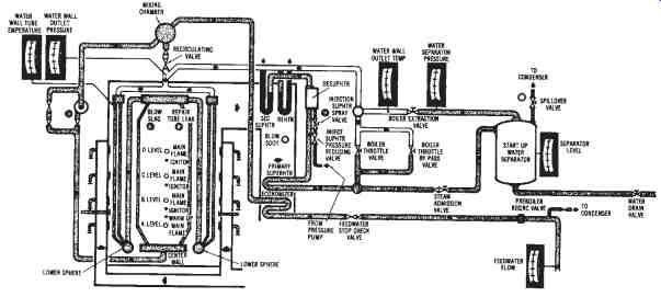
FIG. 10. The boiler-water subsystem (Omnidata, Inc.)

FIG. 11. The steam and turbine subsystem (Omnidata, Inc.)
Oil-fired System Simulator
An oil-fired electrical power system simulator is very similar to the coal-fired system. The subsystems are identical to those used in the coal-fired system except, of course, that there is no coal-pulverizing system. These subsystems may be studied to learn the various parts of a power system in more detail.