AMAZON multi-meters discounts AMAZON oscilloscope discounts
1. Introduction
This section outlines a program for testing and commissioning of protective and overcurrent relays and instrument transformers used in switchgear and/ or standalone applications. The frequency of testing of these devices may be dependent upon many factors; however, an annual schedule of inspection and maintenance is recommended for electromechanical and induction relays; and inspection and testing of solid-state and microprocessor relays when trouble is indicated or upon unanticipated operation of these relays.
Before a successful maintenance and inspection program can be implemented, it is essential that the personnel performing or evaluating inspection and maintenance should be thoroughly familiar with the types of protective relays, devices, and auxiliary equipment. Therefore, in this section a brief overview of protective and overcurrent relays, and instrument trans formers is given for the reader to become familiar with the system equipment. The maintenance and testing of electromechanical and induction relays involves inspection, mechanical adjustment, and electrical tests.
Similarly, the maintenance and testing of solid-state and microprocessor relays involves inspection and self-diagnostics and tests. Since the protective equipment plays such an important role for the safety of personnel and property, they should be given special attention. Moreover, since these devices operate during abnormal conditions on the power system, the only way to assure correct operation is by a comprehensive inspection, maintenance, and testing program.
2. Instrument Transformers
Instrument transformers are essential parts of many electrical metering and relaying systems. The quality of instrument transformers will affect directly the overall accuracy and performance of these systems. Instrument transformer performance is critical in protective relaying, since the relays can only be as good as the instrument transformers. They serve two basic functions:
To change the magnitude (but not the nature) of primary voltage and current to secondary values to 120 V and 5 or 1 A where relays, meters, or other devices can be applied To provide isolation between primary and secondary circuit for equipment and safety of personnel When relays compare the sum or difference of two or more currents or the inter action of voltages and currents, the relative direction of the current must be known. The direction of current flow can be determined by knowing the instrument transformer polarity. Polarity markings are normally shown on instrument transformers; however, they can be determined in the field if necessary. Several aspects of current and voltage instrument transformers are discussed next.
2.1 Current Transformers
Current transformers (CTs) are designed for connection in the primary circuit (either in series or around the primary circuit). The secondary current of the transformer bears a known relationship with the primary current. Any change in the primary current is reflected in the secondary circuit. Relays, meters, and other devices are connected to the secondary terminals of the CTs. CTs are made in many different ratios, different voltage insulation systems, and for different environmental conditions such as indoor or outdoor use. Generally, the following types of construction are used for CTs.
Wound type: • In this type more than one primary turn is frequently used to obtain low exciting current and high accuracy. The usual current ratings for this type of transformer are 800A and below.
Bar-primary type: • In this type, the primary consists of a single bar extending through the core, which is connected in series with the circuit conductor. This type of construction is suited to withstand the stresses of heavy overcurrent. The usual current rating for this type of transformer is 1200 A or above in order to provide sufficient ampere-turns for good accuracy.
Window type: • The window-type CT contains no primary winding.
The CT has an insulated hole through the core and secondary windings. The circuit conductor is inserted through the window of the CT, and thus this conductor then becomes the primary of the CT.
Bushing type: • The bushing-type CT is similar to the window-type.
It has a circular core that is designed to it on the bushing of a power transformer, circuit breaker, or other apparatus. The secondary windings are wound on the circular core and can be tapped to give multiple ratios. This transformer is mostly used for relaying purposes where high accuracy at normal current value is not extremely important.
Double-secondary type: • A double-secondary transformer is actually two transformers, each transformer having its own core. This type of transformer occupies less space than two single-secondary winding transformers. The double-secondary winding transformer permits instruments, relays, or other devices to be separated if required.
Split-core type: • This is a window-type CT with hinged cores, which permit them to be installed on buses or other circuits.
Air-core type: • The air-core CT is used where saturation of the iron core due to high fault currents is a problem. The air-core transformer has relative constant error over a wide range of overcurrent and transient conditions.
Tripping transformers: • Several types of small and inexpensive transformers are available for protective control functions. These transformers are not made with the same accuracy as instrument transformers.
Auxiliary transformers: • Auxiliary transformers are used to adjust the difference in ratio between different CTs. These transformers are connected in the secondary circuits of main CTs.
2.1.1 CT Accuracy Standards
CTs can be divided into two categories for purposes of establishing accuracy standards: (1) accuracy standard for metering CTs, and (2) accuracy standard for relaying CTs. Since accuracy is a function of the burden on the CT, standard burdens have been established. Accuracy has been established at various burden values. The standard burdens established by American National Standard Institute (ANSI) C57.13-1993(R2003) are shown in Table 9.1. The performance rating is based on 5A secondary current unless otherwise specified.
TABLE 1 Standard Burdens for CTs
2.1.2 Accuracy Classes for Metering
The ANSI accuracy classes for metering state that the transformer correction factor (TCF) should be within specified limits when the power factor of the metered load is from 0.6 to 1.0 lagging for a specified standard burden, at 100% of rated primary current. CTs for metering service have accuracy classes of 0.3%, 0.6%, and 1.2%.
2.1.3 Accuracy Classes for Relaying
The ANSI standard 57.13-1993 has standardized on the accuracy classes and the conditions under which instrument transformers are to be applied. Prior to 1968, the accuracy classes and the conditions under which the instrument transformers were applied were based on ANSI standard C57.13-1954. The ANSI standard 57.13-1954 was revised in 1968 and this standard set one accuracy class, instead of the two that was in the older standard. The revised standard also changed the designations for the older class of CTs. Hence, the ANSI 57.13-1968 standard is different than the older standard of ANSI 57.13-1954 in many respects. Since many older CTs and voltage transformers (VTs) are still in use today, it is appropriate to discuss the older and revised ANSI C57.13 standards.
Older standard (ANSI C57.13-1954): In this standard, the accuracy ratings were on the basis of the standard secondary terminal voltage, a transformer would deliver without exceeding a standard percent ratio error. The classification of CT performance was based on the ratio error at 5 to 20 times secondary current. Therefore, the CTs were divided into classes, H and L. Class H had a nearly constant percentage ratio error when delivering a fixed secondary volt age over a wide range of secondary current. Class L had a nearly constant magnitude error (variable percentage error) when delivering a fixed secondary voltage over a wide range of secondary current. Standard percent ratio error classes for class H CTs were 2.5% and 10%, whereas for class L CTs, the standard percent ratio error was 10%. Secondary voltages were 10, 20, 50, 100, 200, 400, and 800 V. For example, CTs were classified as 2.5 H 200 or 10 L 200. The first term described the maximum percent ratio error, the second term (H or L) described the transformer performance characteristics, and the third term described the secondary voltage. The class H transformer could deliver a secondary voltage equal to its voltage class at 5 to 20 times secondary rated current. A class L CT, on the other hand, could only deliver a secondary volt age within its voltage class at 5 to 20 times secondary rated current at fixed burden. In other words, class L cannot be used with proportionately higher burdens at lower secondary current without exceeding its classified ratio error.
Newer standard (ANSI 57.13-1968): A relaying accuracy under the new standard is designated by symbols C and T.
C-type CTs have single primary turn and distributed secondary windings. For C-type CTs the ratio error can be calculated. Majority of these CTs are bushing type and are rated at 600 V since they do not have any physical connection with the primary circuit.
T-type CTs are constructed with more than one primary turn and undistributed windings. The primary windings are insulated and braced for the primary voltage. Because of the physical space required and the fringing effects of nonuniformly distributed winding, because there is flux that does not link both the primary and secondary windings. The leakage flux has significant effect on the CT performance and it is not possible to calculate the ratio correction error using the burden and excitation characteristics. Therefore, the ratio correction must be determined by test for the T-type CTs.
The secondary terminal voltage rating for the C-type and T-type CTs is the voltage which the transformer will deliver to a standard burden (as listed in Table 9.1) at 20 times normal secondary current.
The transformer ratio error must be limited to 10% for all currents from 1 to 20 times normal current for burdens not to exceed those listed in Table 9.1.
K-type:• The K classification was established in the 1993 revision of the C57.13 standard. The K-type CTs are designed to have knee-point voltage at least 70% of the secondary terminal voltage rating.
The K-type is similar to C-type CTs, i.e., their design is based on the principle that the leakage flux in the core does not have an appreciable effect on the ratio of the CT within the limits of current and burden.
To specify a CT under the new standards, one needs only to select either a class C or T transformer and then specify the burden. The first term of the burden classification of a CT identifies the construction type of CTs as discussed in Sections 2.1, and the second term describes the voltage rating that can be delivered by the full winding at 20 times rated secondary current with out exceeding 10% ratio correction (error). The ANSI voltage rating applies to the full winding, and if less than full winding is used, the voltage rating is then reduced in proportion to turns used. As an example, a CT C200 or T200 means that a ratio correction error will not exceed 10% for values from 1 to 20 times rated secondary current (5 A) with a standard 2.0 Ohm burden.
The C classification covers bushing transformers, and the T classification covers any other transformer The secondary voltage values are 10, 20, 50, 100, 200, 400, and 800 V based on 1 to 20 times the normal current standard burdens listed in Table 1
TABLE 2 ANSI Standard Burdens for VTs
2.2 Voltage (Potential) Transformers
VTs are designed for connecting line-to-line or line-to-neutral. The purpose of the VT is to provide an isolated secondary voltage that is an exact proportionate representation of primary voltage. However, transformers draw core-magnetizing current from the primary circuit, and a constant error results independent of the burden connected to it. Also, variable error results due to load or burden current flowing through the effective impedance of the transformer. The total error is the sum of these two errors under any burden condition. The ANSI standard C57.13-1993(R2003) lists the classification of VTs encountered in service as W, X, Y, Z, and ZZ. The standard burden designations are shown in Table 2 for these VTs.
Accuracy classes are based on the requirement that the TCF be within specified limits when the power factor of the metered load is between 0.6 and 1.0 lagging for a specified burden and at voltages from 90% to 110% of rated transformer voltage. The ANSI accuracy classes for VTs are shown in Table 3.
The ratings of VTs encompass the following:
• Insulation class and basic impulse level
• Rated primary voltage and ratio
• Accuracy ratings at standard burdens
• Thermal burden, that is, the maximum burden the transformer can carry at rated secondary voltage without exceeding its temperature rise, above 30°C ambient.
TABLE 3 ANSI Accuracy Classes for VTs
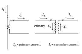
FIG. 1 Polarity marking of transformers.
2.3 Polarity of Instrument Transformers
Instrument transformers are marked to indicate the instantaneous direction of primary and secondary currents. Usually, one primary and one secondary terminal are marked with a cross (×) or a dot (•) or a square (¦) to indicate the polarity. The following conventions apply to either current or VTs with sub tractive or additive polarity.
The current flowing out at the polarity marked terminal on the secondary side is nearly in phase with the current flowing in at the polarity marked terminal on the primary. This is shown in FIG. 1.
The voltage drop from the polarity to the nonpolarity marked terminals on the primary side is nearly in phase with the voltage drop from the polarity to the nonpolarity marked terminals on the secondary side.
2.3.1 Testing for Polarity of Instrument Transformers
The polarity of instrument transformers can be determined by direct current (DC) or alternating current (AC) tests.
DC test
Connect a DC permanent magnet ammeter of 5 A capacity or less (depending on the transformer ratio) across the CT secondary terminal. The marked secondary terminal of the transformer should be connected to the plus (+) ammeter terminal. Then connect a 7.5 V battery to the primary side such that the negative terminal is connected to the unmarked primary terminal of the transformer. Make an instantaneous contact with the positive battery terminal to the marked terminal of the transformer. A kick or deflection will be noticed on the ammeter. If the kick is in the positive direction (i.e., upscale) upon making the contact, the transformer leads are correctly marked. If the initial kick is in the negative direction (i.e., downscale), the polarity markings are not correct. See FIG. 13 (also refer to Figure 5.19 in Section 5) for connections of this test.
VTs can be tested by using a DC permanent magnet moving-coil-type volt meter having a 150 V scale. The test is performed in a manner similar to the test for CTs, except that the voltmeter is connected across the high-voltage terminals of the transformer first, and then the battery voltage is applied to the low-voltage terminals.
AC tests
The following AC methods are used for determining polarity.
Excitation test
This test consists of exciting the transformer high-voltage winding with low voltage and comparing the voltage across the winding with voltage across both windings in series. This method is not very practical with transformers with high ratios such as 100:1, because the difference between the two volt ages is very small, which cannot be measured with ordinary instruments.
Moreover, there is always a danger of exciting the low-voltage winding instead of the high-voltage winding, thereby producing dangerous voltages on the transformer.
Substitution method
This method involves using a transformer with known polarity. Make connections as for the known polarity transformer, as shown in FIG. 2a and b, and then connect the transformer whose polarity is to be determined. If the ammeter needle deflects in the same direction in both cases, the polarities of two transformers are the same. By knowing the polarity of the first transformer, the polarity of the second transformer is then determined.
Differential method
The differential method involves exciting the primaries of both transformers (known and unknown polarities) and making a differential measurement with an ammeter or voltmeter. When the secondaries of two VTs are connected in series, the readings should be the sum of the voltages of two transformers. Similarly, when the two current secondaries of the transformers are connected in parallel, the ammeter should read the sum of the currents in two transformers. The connections are shown in FIG. 3a and b.
FIG. 2 Connection for substitution method.
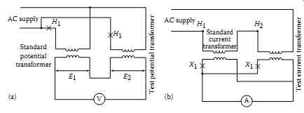
FIG. 3 Connection for differential method.
2.4 Testing for Ratio of Instrument Transformers
The ratio of instrument transformers can be determined by two generally accepted tests.
Voltage method test
A suitable AC voltage, below saturation i.e., below the knee point of the CT saturation curve, is connected to the full secondary winding and a high impedance (20,000 O/V or greater) low-range voltmeter is connected in the primary of the CT. The primary voltage is read on the low-range voltmeter as the secondary voltage is applied to the CT. The turn ratio is approximately equal to the voltage ratio. In most low and medium-ratio bushing CTs, the saturation level is achieved at about 1 V per turn. The saturation level may be lower than 0.5 V per turn in high-ratio generator CTs and window-type CTs used in metal clad switchgear. For very high-ratio CTs, an application of test voltage even lower than 0.5 V per turn may be required to avoid personnel hazard and possible damage to equipment.
Current method test
This method requires a source of high current and an additional CT of known ratio with its own ammeter and a second ammeter for the CT under test. The test is conducted by injecting the high current test source to a series of values over the desired range and recording the two secondary current readings.
The ratio of the CT under test is equal to the turns ratio of the reference CT multiplied by the ratio of the reference CT secondary current to the test transformer secondary current. When conducting this test avoid using multiple turns of the test conductor through the center of the window-type CT to reduce its ratio because it may produce an abnormal secondary leakage reactance and misleading results in the ratio measurement. The effect is unpredictable and although small with distributed winding CTs with low secondary burden, it may be produce a large error in older CTs particularly when high burdens are connected.
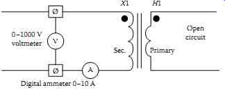
FIG. 4 Excitation test circuit of a CT.
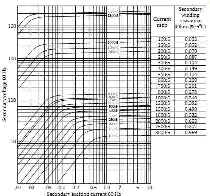
FIG. 5 Typical excitation curve for C class, multi-ratio CT. (Courtesy
of Instrument Transformers, Inc., Clearwater, FL.)
Excitation test
Excitation voltage and current tests can be made on both C (distributed winding) and T class (non-distributed winding) CTs in order to assess if the CT is performing correctly and to determine if deviations are present.
To perform this test, an AC voltage is applied to the secondary winding with the primary winding open-circuited as is shown in FIG. 4. The voltage applied to the secondary winding is varied, and the current drawn by the winding at each selected voltage value is recorded. A curve is plot ted of the secondary voltage versus current for comparison with the original manufacturer's excitation (saturation) curve. A sample of excitation curves of multiratio CT are shown in FIG. 5. The readings near the knee of the excitation curve are important when plotting this curve. For multitap ratio CTs, the highest tap should be used provided that the cur rent transformer can be saturated at the selected tap with the test equipment available. The ammeter used for this test should be an root mean-square (rms) instrument and the voltmeter should be an average reading voltmeter calibrated to give the same numerical indication as an rms voltmeter. Deviations from expected results or in comparison to the manufacturer data may indicate a turn-to-turn short, distorted wave form of test voltage, or the presence of a conducting path around the CT core. Caution should be taken to minimize energizing the CT at voltages above the knee of the excitation curve any longer than is necessary to take the readings. This test can also be conducted by energizing the CT primary winding from a high-current test source and plotting the data as primary exciting current versus secondary open-circuited voltage. The current must be divided by the CT ratio for comparison with the manufacturer's excitation curve data.
2.5 Winding and Lead Resistance Measurements
The internal resistance of CT windings and external impedance (including lead resistance) are required for relay setting calculations, and for calculating ratio correction error when applying CTs. The internal winding resistance and the lead resistance can be calculated or measured with a resistance bridge. If it is desired to separate the winding resistance and lead resistance, the resistance of a full winding and of a tap then should be measured. All measurements should be made at the CT short-circuiting terminal block.
After completion of this test, the CT should be demagnetized to remove any residual magnetism as discussed under Section 2.7.
2.6 Burden Measurements
For relay applications and for calculating CT ratio correction factors, burden measurements may be necessary. In such cases, the total burden of the circuit, which is the sum of the internal CT burden and the external connected burden must be determined. The internal burden is the resistance of secondary winding and the lead resistance from the winding to the short-circuiting terminal block as discussed in Section 2.5. The internal burden can be converted to volt-amperes at rated secondary current. The external burden can be measured in volt-amperes by measuring the voltage required to drive the rated current through the connected burden (load).
2.7 CT Remanence
The residual magnetism of a CT is known as remanence. The performance of both class C and T CTs is influenced by remanence. The core of the CT is subject to hysteresis, i.e., when current is interrupted the flux density in the core does not become zero when current does. When flux in the core is high due to high current or because the current contains a high DC component and when this current is interrupted, the residual magnetism in the core will be high, possibly being above the flux equivalent of the knee point on the excitation curve as shown in FIG. 5. When the CT is next energized, the flux changes will begin from the remanence value and therefore may lead to the saturation of the CT. When this occurs, much of the primary current is used for exciting the core, and thereby significantly reducing and distorting the secondary output. This condition can be corrected by demagnetizing the core of the CT. This can be accomplished by applying a suitable variable alternating voltage to the secondary, with initial magnitude sufficient to force the flux density above the saturation point, and then decreasing the applied voltage slowly and continuously to zero. Test connections are identical to those as shown in FIG. 4 for performing this test.
2.8 Grounding of CT
It is common practice to connect the secondary of the instrument (current and voltage) transformers to the station or substation ground system. The primary purpose of grounding is for personnel safety and correct performance of the instrument transformers, relays, meters, and other equipment connected to the instrument transformer secondaries. The grounding point in the instrument transformer secondary circuit should be located electrically at one end of the secondary winding of each instrument transformer and physically at the first point of switchboard or relay panel of the instrument transformer secondary circuit. The following are some examples for grounding instrument transformers.
1. A single instrument transformer secondary winding should be connected to a single ground.
2. Where more than one instrument transformer is used, such as three single-phase transformers wye-connected to form a three-phase connection, the common point of the secondary windings of all instrument transformers should be connected to a single ground.
3. The secondary circuit of multi-instrument transformers where no common point of connection is available for all of the transformer secondaries, such as delta-connected transformers, should have the common point between the greatest number of the secondary windings connected to ground.
4. When secondary windings of more than one instrument transformers are interconnected and do not have a common neutral connection, then the common secondary neutral connection for the greatest number of these transformers should be the point of connection to ground.
5. The grounding conductor for instrument transformers should be as large, or larger than the secondary phase conductors. The grounding conductor should never be smaller than number 12 AWG copper, or equal, for grounding of instrument transformers.
6. CTs that are not used should have the full winding shorted at the CT location and grounded.
2.9 Maintenance and Testing of Instrument Transformers
The following general recommendations are offered to supplement the manufacturer's instructions.
General maintenance If instrument transformers are allowed to remain out of service for a long period of time, they should be dried before being put into service Instrument transformers containing oil or synthetic dielectrics should be tested periodically to determine the breakdown voltage remains at 26 kV or above.
The secondaries of CTs that are not connected to relays, meters, and the like, should have their secondaries shorted and grounded as mentioned in Section 2.8
The secondary circuits and cases of all instrument transformers should be grounded with at least a number 12 AWG conductor as discussed earlier in Sections 2.8
Testing
Routine testing as described below should be performed on instrument transformers.
General purpose instrument transformers
Ratio and phase angle tests should be made on CTs for metering at 100% and 10% of rated primary current, when energized at rated frequency with maximum standard burden for which the transformer is rated
The turns ratio and polarity tests should be made on CTs for relaying to ensure that they have the correct turns ratio and relaying accuracy
Revenue metering instrument transformer
Calibrate all meters at 10%, 50%, and 90% of full scale. Instruments used for calibration of test equipment should have precision of no more than 50% of the instrument being tested.
Calibrate watt-hour meters to 0.5%.
Verify all instrument multipliers.