AMAZON multi-meters discounts AMAZON oscilloscope discounts
7. Preventive Maintenance of Transformers
The objective of this section is to outline the recommended work practices that are usually performed for preventive maintenance of transformers. The recommended procedures specified in this section do not pertain to the major overhaul and repair of a transformer. However, many tasks performed during routine maintenance and major overhaul of a transformer may be the same. The maintenance practices discussed in this section are applicable to a transformer that has not reached an advanced stage of deterioration.
Moreover, these recommendations are written for the average conditions under which the transformer is required to perform and operate. It is further implied that all personnel associated with the maintenance are suitably trained and have experience in the maintenance of transformers.
The recommended practices offered in this section are similar to those that manufacturers recommend for their equipment. If detailed instructions are required, the reader should consult the instructions manual of the manufacturer. The preventative maintenance of transformer involves routine inspection, adjustment, testing, minor repairs, and special handling instructions. In addition, the trouble-free operation of the equipment over its life is dependent upon proper installation, operation, and maintenance, which are discussed in Section 5.7.1.
7.1 Transformer Installation, Acceptance, and Maintenance
The successful operation of transformers is dependent on proper installation, loading, and maintenance, as well as on proper design and manufacture. As is with all electrical apparatus, neglecting of certain fundamental requirements may lead to serious troubles, if not to the loss of the equipment. The objective of transformer maintenance philosophy can be described as follows:
7.1.1 Unscheduled Maintenance
This philosophy is based on reactionary mode of operation. That is to say, maintain the equipment when it breaks down, otherwise leave it alone.
7.1.2 Ordinary Maintenance
This philosophy subscribes to making irregular visual inspection and making repairs, adjustments, and replacements as necessary.
7.1.3 Protective Maintenance
This philosophy consists of performing preventive maintenance, predictive maintenance, and corrective maintenance. The preventive maintenance involves schedule maintenance and testing on a regular basis. Predictive maintenance involves additional monitoring and testing, where as corrective maintenance involves repairing and restoring transformer integrity to its original condition when degraded conditions are discovered.
The objective of the protective maintenance of transformers is to control and prevent severe oil and winding (paper) insulation deterioration. Mineral oil and paper insulation of the winding are affected by moisture, oxygen, heat, and other catalytic agents such as copper, iron, electric stress, and so on. The end result is that oxidation takes place in the oil which leads to sludging of the transformer. In sealed units ingress of moisture via atmosphere or seal leaks must be prevented. Moisture will reduce the dielectric strength of both the oil and the winding insulation systems. In addition, excessive heating of the transformer will cause the paper (winding insulation) to decompose (accelerate aging) which in-turn produces moisture (i.e., break up of cellulose fibers results in freeing hydrogen and oxygen atoms which combine to form H2O). Increased moisture formed in the paper not only reduces the insulating strength of the paper but also, as temperature rises, the moisture will migrate from the paper insulation to the oil and decreasing its dielectric strength.
The first step is to build transformer designs to keep moisture and oxygen out of transformers. The next step is to operate transformers so that they are not operated beyond their temperature ratings and limits. In addition to the above, the severity of deterioration should be controlled by monitoring and testing transformer insulation systems on periodic basis, and take corrective actions to restore transformer to its original condition. This philosophy can be summarized by the following:
1. Control transformer heat
2. Inspect and maintain transformer auxiliary devices
3. Test and maintain transformer insulation systems
4. Maintain transformer bushing insulation
5. Maintain transformer protective coating
These topics are discussed next under installation, maintenance, and testing of transformers. The transformers are divided into dry and liquid types for the purposes of this section.
7.2 Dry-Type Transformers
7.2.1 Installation
Factors that should be kept clearly in mind in locating dry-type transformers are accessibility, ventilation, and atmospheric conditions. Ventilated dry-type transformers (FIG. 14) normally are designed for application indoors in dry locations. They will operate successfully where the humidity may be high, but under this condition it may be necessary to take precautions to keep them dry if they are shut down for appreciable periods. Locations where there is dripping water should be avoided. If this is not possible, suitable protection should be provided to prevent water from entering the transformer case.
Precautions should be taken to guard against accidental entrance of water, such as might occur from an open window, by a break in a water or steam line, or from use of water near the transformers. Adequate ventilation is essential for the proper cooling of transformers. Clean, dry air is desirable. Filtered air may reduce maintenance if the location presents a particular problem. When transformers are installed in vaults or other restricted spaces, sufficient ventilation should be provided to hold the air temperature within established limits when measured near the transformer inlets. This usually will require a minimum of 100 ft^3 of air per minute per kilowatt (kW) of transformer loss.
The area of ventilating openings required depends on the height of vault. The location of openings, and the maximum loads to be carried by the transformers. For self-cooled transformers, the required effective area should be at least 1 ft for each inlet and outlet per 100 kVA of rated transformer capacity, after
deduction of the area occupied by screens, gratings, or louvers.
Ventilated dry-type transformers should be installed in locations free from unusual dust-producing mediums or chemical fumes. Transformers above 75 kVA should be located at least 12 in. from walls or other obstructions that might prevent free circulation of air through and around each unit. The distance between adjacent transformers should not be less than this value.
Smaller transformers can be mounted directly on the wall but should still be mounted at least 12 in. apart. Also, accessibility for maintenance should be taken into account in locating a transformer. If the transformer is to be located near combustible materials, the minimum separations established by the National Electrical Code (NEC) should be maintained.
The transformer case is designed to prevent the entrance of most small animals and foreign objects. However, in some locations it may be necessary to give consideration to additional protection. In general, a flat, level industrial floor is adequate and no special preparation is necessary because of the base construction used on these transformers, which completely eliminates the complicated process of grouting sills into concrete floors. If noise is a factor in the location and operation of any transformer, special consideration should be given to the installation of the equipment.
The impulse strength of these transformers is less than that of liquid immersed units of the same voltage class. If there is any likelihood that transformers will be exposed to lightning or severe switching surges, adequate protective equipment should be provided.
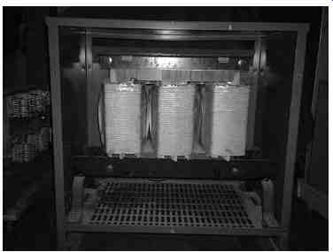
FIG. 14 A 150 kVA ventilated dry-type general purpose transformer with
front cover removed to show core-coil assembly.
Transformers of standard temperature rise are designed to operate at altitudes up to and including 3300 ft. Dry-type transformers are dependent upon air for dissipation of their heat losses; consequently, the effect of decreased air density due to high altitude will increase the transformer temperature. Standard transformers can be used at altitudes greater than 3300 ft if the load to be carried is reduced below nameplate rating as follows:
If the transformer is dry type, self-cooled, class AA, reduce the nameplate rating by 0.3% for each 330 ft above the altitude of 3300 ft.
If the transformer is dry type, forced air cooled, class AA/FA, reduce the nameplate rating by 0.5% for each 330 ft above the altitude of 3300 ft.
If the maximum 24 h average temperature of the cooling air is reduced below design levels, the altitude limitation of 3300 ft can be safely exceeded without reducing the nameplate rating of the transformer within the limitations of TABLE--3.
7.2.2 Inspection
New transformers should be inspected for damage during shipment when received. Examination should be made before removing from cars or trucks, and if any injury is evident or any indication of rough handling is visible, a claim should be i led with the carrier at once and the manufacturer should be notified.
Subsequently, covers or panels should be removed and an internal inspection made for injury or displacement of parts, loose or broken connections, cracked porcelain, dirt or foreign material, and for the presence of free water or moisture. Corrective measures should be taken where necessary. Shipping braces should be removed if provided. After a transformer is moved, or if it is stored before installation, this inspection should be repeated before placing the transformer in service.
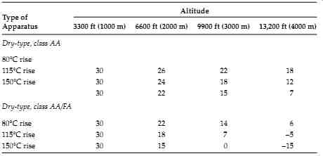
TABLE--3 Maximum 24 h Average Temperature of Cooling Air (°C)
After making all the necessary primary and secondary connections, the transformer should be thoroughly inspected. Before placing in service, the operation of fans, motors, thermal relays, and other auxiliary devices should be checked. All bolted connections that may have loosened in shipment must be tightened before energizing. The case and core assembly of these transformers should be permanently and adequately grounded.
7.2.3 Acceptance Tests
After the transformer has been installed, the following tests should be con ducted for acceptance:
Insulation resistance (IR) test: The IR test is of value for future comparative purposes and also for determining the suitability of the transformer of energizing or application of the high-potential (hi-pot) test. The IR test must be successfully completed for factory warranty to be valid. The IR test must be conducted immediately prior to energizing the transformer or beginning the high potential test.
These values, corrected to factory test temperature of 20°C, must be either 1000 MOhm or equal to or greater than the values shown in the TABLE--4, or a minimum of one half or more of factory test values. If the corrected test values at 20°C are less than the minimum of the values discussed above, then the transformer insulation condition is questionable. In the absence of reliable previous test data, the following formula may be used for single-phase transformers, or single winding of a three-phase transformer for calculating the IR values.
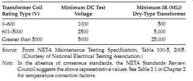 TABLE--4 Dry-Type Transformer IR Values
IR=CE/ kVA, where...
IR is the minimum 1 min 500 V DC IR in MO from winding to ground, with other winding or windings guarded, or winding to winding with core guarded C = 30 at 20°C measurements (C = 16 for tests of winding with other winding or windings grounded)
E is the voltage rating of winding under test kVA is the rated capacity of winding under test If the transformer under test is of the three-phase type, and all three individual windings are being tested as one, then:
E is the voltage rating of one of the single-phase windings (phase to-phase for delta-connected units and phase-to-neutral for star-connected units kVA is the rated capacity of the three-phase winding under test Polarization index (PI) test: This is an extension of the IR test. In this test, the two IR measurements are taken, the first reading at 1 min and the second reading at 10 min. Then the ratio of the 10 min reading to 1 min reading is calculated to give the PI dielectric absorption value.
A PI of winding-to-winding and winding-to-ground should be determined. A PI below 2 is indicative of insulation deterioration and cause for further investigation.
AC hi-pot (dielectric) test: The dielectric test imposes a stress on the insulation since the dielectric test voltage is higher than the normal operating voltage. The IR test must be successfully completed immediately before performing the dielectric test to prevent the possibility of transformer failure due to moisture. The dielectric test supplements the IR tests by determining the suitability of the transformer for operation at rated voltage. Field test voltages should not exceed 75% of factory test values. The hi-pot test set must be variable to allow a gradual increase of test voltage from zero and a gradual decrease after the test is completed. These test values are shown in TABLE--5.
Transformer turns ratio (TTR) test: The TTR test is used to determine the turns ratio of the transformer. It measures the number of turns of the primary winding with respect to the number of turns in secondary winding. The accepted values of the TTR test shall be not greater than 0.5% as compared with calculated values.
Insulation power factor (PF) (dissipation factor) test: This test measures the watt loss in the insulation under test. Since it is an AC voltage test, it accurately indicates the wetness of the winding insulation and corona problems. This test can be conducted as PF tip-up test for dry type transformers to further distinguish between a moisture or carbonization problem.
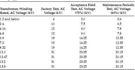
TABLE--5 Dielectric Test Value for Acceptance and Periodic Maintenance
of Dry-Type Transformers
7.2.4 Maintenance
Like other electric equipment, these transformers require maintenance from time to time to assure successful operation. Inspection should be made at regular intervals and corrective measures taken when necessary to assure the most satisfactory service from this equipment. The frequency of inspection depends on operating conditions. For clean, dry locations, an inspection annually, or after a longer period, may be sufficient. However, for other locations, such as may be encountered where the air is contaminated with dust or chemical fumes, an inspection at 3 or 6 month intervals may be required.
Usually, after the first few inspection periods, a definite schedule can be set up based on the existing conditions.
With the transformer de-energized, covers over openings in the case should be removed. Inspections should be made for dirt, especially accumulations in insulating surfaces or those which tend to restrict air flow, for loose connections, for the condition of tap changers or terminal boards, and for the general condition of the transformer. Observation should be made for signs of over heating and of voltage creepage over insulating surfaces, as evidenced by tracking or carbonization. Evidence of rusting, corrosion, and deterioration of the paint should be checked and corrective measures taken where necessary.
Fans, motors, and other auxiliary devices should be inspected and serviced.
Cleaning: If excessive accumulations of dirt are found on the transformer windings or insulators when the transformer is inspected, the dirt should be removed to permit free circulation of air and to guard against the possibility of insulation breakdowns. Particular attention should be given to cleaning top and bottom ends of winding assemblies and to cleaning out ventilating ducts.
The windings may be cleaned with a vacuum cleaner, blower, or with compressed air. The use of a vacuum cleaner is preferred as the first step in cleaning, followed by the use of compressed air or nitrogen. The com pressed air or nitrogen should be clean and dry and should be applied at a relatively low pressure (not over 25 psi). Lead supports, tap changers and terminal boards, bushings, and other major insulating surfaces should be brushed or wiped with a dry cloth. The use of liquid cleaners is undesirable because some of them have a solvent or deteriorating effect on most insulating materials.
Testing for routine maintenance: Following are the tests that are required for routine maintenance of dry-type transformers.
IR test of winding-to-winding and winding-to-ground. This test is similar to the test listed under installation and acceptance.
Dielectric absorption test should be made winding-to-winding and winding-to-ground for 10 min. The PI should be above 2.0 for acceptable limits.
Turns ratio test (TTR) should be conducted similarly to that under acceptance.
AC overpotential test should be made on all high- and low-voltage windings-to-ground. This is an optional test for routine maintenance testing. The recommended values of test voltage are shown in TABLE--4.
Insulation PF test can be conducted for each winding-to-ground and winding-to-winding. The acceptable value is less than 3%.
7.2.5 Drying-Out Methods
For the purpose of drying out, transformers can be considered as consisting of core and coil assembly. When it is necessary to dry out a transformer before installation or after an extended shutdown under relatively high humidity conditions, one of the following methods may be used.
- External heat
- Internal heat
- External and internal heat
Before applying any of these methods, free moisture should be blown or wiped off the windings to reduce the time of the drying period.
Drying by external heat: External heat may be applied to the transformer by one of the following methods:
By directing heated air into the bottom air inlets of the transformer case
By placing the core and coil assembly in a nonflammable box with openings at the top and bottom through which heated air can be circulated By placing the core and coil assembly in a suitably ventilated oven By placing incandescent lamps in the transformer enclosure It is important that most of the heated air be blown through the winding ducts and not around the sides. Good ventilation is essential in order that condensation will not take place in the transformer itself or inside the case.
A sufficient quantity of air should be used to assure approximately equal inlet and outlet temperatures.
When using either of the first two external heating methods, heat may be obtained by the use of resistance grids or space heaters. These may either be located inside the case or box or may be placed outside and the heat blown into the bottom of the case or box. The core or coil assembly should be care fully protected against direct radiation from the heaters. It is recommended that the air temperature should not exceed 110°C.
Drying by internal heat: This method is relatively slow and should not be used if one of the other two methods is available. The transformer should be located to allow free circulation of air through the coils from the bottom to the top of the case. One winding should be short circuited, and sufficient voltage at normal frequency should be applied to the other winding to circulate approximately normal current.
It is recommended that the winding temperature not be allowed to exceed 100°C, as measured by resistance or by thermometers placed in the ducts between the windings. The thermometers should be of the spirit type, because mercury thermometers give erroneous readings due to the generation of heat in the mercury as a result of induced eddy currents. The end terminals of the windings (and not the taps) must be used in order to circulate current through the entire winding. Proper precautions should be taken to protect the operator from dangerous voltages.
Drying by external and internal heat: This is a combination of the two methods previously described and is by far the quickest method. The transformer core and coil assembly should be placed in a nonflammable box, or kept in its own case if suitable; external heat is applied as described in the first method, and current is circulated through the windings as described in the second method. The current required will be considerably less than when no external heating is used but should be sufficient to produce the desired tempera ture of the windings. It is recommended that the temperatures attained do not exceed those stated in previous two methods. Drying time depends on the condition of the transformer, size, voltage, amount of moisture absorbed, and the method of drying used.
The measurement of IR is of value in determining the status of drying.
Measurements should be taken before starting the drying process and at 2 h intervals during drying. The initial value, if taken at ordinary temperatures, may be high even though the insulation may not be dry. Because IR varies inversely with temperature, the transformer temperature should be kept approximately constant during the drying period to obtain comparative readings. As the transformer is heated, the presence of moisture will be evident by the rapid drop in resistance measurement. Following this period the IR will generally increase gradually until near the end of the drying period, when it will increase more rapidly. Sometimes it will rise and fall through a short range before steadying, because moisture in the interior of the insulation is working out through the initially dried portions. A curve with time as abscissa and resistance as ordinate should be plotted and the run should be continued until the resistance levels off and remains relatively constant for 3 to 4 h.
IR measurements should be taken for each winding-to-ground, with all windings grounded except the one being tested. Before taking IR measurements, the current should be interrupted and the winding should be short circuited and grounded for at least 1 min to drain off any static charge. All readings should be for the same time of application of test voltage, preferably 1 min.
Constant attendance during the drying process is desirable. It is advisable to have a suitable fire extinguisher convenient for use in the event of an emergency.
7.2.6 Storage
Ventilated dry-type transformers preferably should be stored in a warm dry location with uniform temperature. Ventilating openings should be covered to keep out dust. If it is necessary to leave a transformer outdoors, it should be thoroughly protected to prevent moisture and foreign material from entering. Condensation and the absorption of moisture can be prevented or greatly reduced by the immediate installation of space heaters or other small electric heaters. If more convenient, incandescent lamps may be substituted for the space heaters. For three-phase transformer rated at 750 kVA and below, use six 150 W lamps; above 750 kVA three phase, use six 300 W lamps or the equivalent. Two lamps should be located under each coil, one on each side of the core. Lamps or heaters should be kept 4-6 in. from transformer coils and should never be allowed to come in contact with transformer coil insulation.
7.3 Liquid-Type Transformer
The following guide covers general recommendations for installation and maintenance of liquid-filled transformers. Many factors listed for dry-type transformers are also applicable to liquid-filled transformers and will not be discussed further.
7.3.1 Installation
The transformer should be installed in accordance with National Fire Protection Association (NFPA) Document 70, NEC Article 450. Because of the ban on askarel for use as a transformer insulating fluid, liquids such as silicone, RTemp, and others are being used. These new liquids have a fire point of not less than 300°C and the NEC has classified these fluids as less flammable. The oil filled transformers, if installed indoor have to be installed in a fireproof vault in accordance with NEC Article 450. Therefore, they are usually installed outdoors with an oil pit (oil containment enclosure) filled with gravel or stones to contain the oil in case of spill. The gravel and stones serve the purpose of inhibiting the oil from pooling in case of fire (see FIG. 15). It is very important that local and NEC regulations be followed when installing transformers filled with these fluids.
One factor of importance for transformer installation is ventilation.
Adequate ventilation should be provided in transformer rooms and vaults to carry transformer heat away. Self-cooled transformers should have adequate (2 to 3 ft) space between each unit to provide free air movement. The ventilation should be dust-free, dry, and noncorrosive, and should not contain any detrimental contaminants. As with dry-type transformers, precautions should be taken to prevent leakage of water into transformer rooms. The tank of the transformer should be permanently grounded by means of 4/0 cable or larger to the substation grounding bus. The transformer should be protected against lightning and other overvoltage conditions by proper lightning arresters.
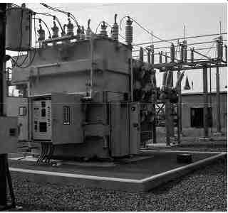
FIG. 15 A three-phase oil filled power transformer.
7.3.2 Inspection
New transformers should be inspected when received for damage during transit. Examination should be made before unloading from the shipping carrier for indication of rough handling and injury to the transformer. After the transformer is removed from the truck or railcar, an internal inspection should be made for displacement of parts, broken or loose connections, dirt or foreign material, and the presence of water or moisture. If oil or transformer fluid was installed at the factory, check the transformer for leaks.
Also check for positive gas pressure if the transformer is equipped with an inert gas. Inspection should include the examination of the transformer case, bushings, anchor and tie rods, grounding straps, drains, covers, valves, and other accessories shipped with the transformer. If internal inspection of the transformer tank is to be conducted, make sure there is enough ventilation in the transformer tank before entering the tank. It is essential that there be at least 16% oxygen content before entering the transformer tank. The inspection port cover should not be opened under wet conditions. It is good practice not to expose the transformer liquid to the atmosphere if the relative humidity is above 65%.
7.3.3 Acceptance Tests
Before a transformer is energized, it should be given the following tests for acceptance.
IR test: The IR test is valuable for determining if the transformer is in good condition and also to establish a benchmark for future comparative tests. The IR values measured are a function of temperature, whether the coils are immersed in the transformer liquid or not, or whether the windings are cold or hot. The measured values should be corrected to 20°C by multiplying them by correction factors given in Table 2.1 of Section 2. The method of measuring IR is by a megohmmeter, commonly called Megger, which indicates the IR directly in million of ohms (or megohms). A Megger having a minimum voltage range of TABLE--6 is recommended for the various voltage- rated transformers. In the absence of consensus standards on what constitutes a good IR value, the Nation Electrical Testing Association (NETA) suggests the values of TABLE--6 be used for acceptance and maintenance testing of transformers.
The measured IR values should be compared to factory test values if avail able for purposes of evaluating the results. It is advisable to watch for the trend to asses whether the measured values remain stable or are heading downward. Although the measured values may be above the minimum value, a downward trend over a period of time may indicate changes which justify further investigation. In the absence of reliable previous test data, the following formula may be used for single-phase transformers, or single transformer winding of three-phase transformer
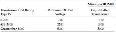
TABLE--6 Liquid-Filled Transformer IR Values
IR=
kVA CE
where IR is the minimum 1 min 500 V DC IR in megohms from winding to-ground, with other winding or windings guarded, or winding-to winding with core guarded C = 30 at 20°C measurements (C = 0.8 for tests of winding with other winding or windings grounded) E is the voltage rating of winding under test kVA is the rated capacity of winding under test If the transformer under test is of the three-phase type, and all three individual windings are being tested as one, then:
E is the voltage rating of one of the single-phase windings (phase-to-phase for delta-connected units and phase-to-neutral for star-connected units kVA is the rated capacity of the three phase winding under test Insulating liquid dielectric test: The insulating liquid should be sampled in accordance with ASTM D-923 standard and tested for determination of its dielectric strength, acidity, moisture, interfacial tension, color, and PF. These tests are performed to ensure that the insulating liquid has not varied from its established levels or that the dielectric strength has not been lowered through accumulation of contaminants and deterioration. The samples for oil and R_temp are taken from the bottom of the tank, where as the samples for askarel and silicone are taken from the top of the tank.
TTR: The TTR is performed to ensure that the turns ratio of the transformer is correct, that is, none of the transformer windings are shorted out. Basically it compares the number of turns in winding with the number of turns in winding 2. The test should be performed for each tap position for transformers equipped with tap changers.
The TTR test can also verify the polarity of the transformer. The TTR test value for acceptance should not be greater than 0.5% as com pared to calculated values (see Section 5.8.2).
Hi-pot test: The hi-pot test (also called the overpotential test) should be made on all high- and low-voltage windings of the transformer to ground. Either AC or DC voltage can be used. However, the accepted practice is to apply either an AC or DC hi-pot test to transformers up to 34 kV. For transformers above 34 kV, only the AC hi-pot test is used. For acceptance of the transformer, the AC hi-pot test can be applied at rated transformer voltage for 3 min. This is a go or no-go test. If the hi-pot voltage is held without any failure or malfunction of the transformer, the transformer is considered to have passed the test.
PF (dissipation factor) test: This test should be performed on important and/or large transformers. This test stresses the insulation in pro portion to the stresses produced in normal service because it is an AC voltage test. The PF tests are discussed in great detail in Section 3 and the reader is urged to refer it (see Section 3.6.1).
Frequency response analysis (FRA): FRA is performed on large power transformers to assess mechanical properties of the windings and core. The purpose of the test is to detect changes in the physical characteristics of the transformer caused by through faults, shipment, repair, or other forces. A voltage signal is applied to the transformer terminals over a wide frequency range and the reflected response is measured. Various techniques for this test are currently being studied. Even so, FRA is beginning to gain wide acceptance in the industry. Refer to Section 5.8.5 for additional information on FRA.
7.3.4 Maintenance
The objective of transformer maintenance is to safeguard against breakdowns by detecting potential causes and eliminating them. Therefore, periodic transformer maintenance will ensure many years of trouble-free operation. The transformer is a very simple, rugged device and is often ignored and forgot ten until transformer failure occurs. However, transformers are a vital link in the electrical distribution system and should be given proper care and attention. Transformer maintenance schedules should be determined according to the critical or noncritical nature of the transformer and the load that is connected to it. Large power transformers are obviously more important than small lighting and distribution transformers; thus they warrant more attention and care. Proper maintenance of the transformer should include routine inspection and repair, transformer liquid maintenance and testing, transformer winding insulation maintenance and testing, and any other special maintenance that is recommended by the manufacturer of the transformer.
A power transformer maintenance and testing guide with recommended frequency is given in TABLE--7.
Routine inspection and repair: Routine inspection and repair of the transformer involve the visual observation of the operating conditions of the transformer and necessary repair. The frequency of these observations depends upon the critical importance of the transformer, the environmental conditions, and/or the operating conditions. Various organizations such as the NFPA, NETA, and manufacturers of transformers have published guides for interval of inspection and what to inspect. Following are typical schedules for conducting a routine inspection.
Load current: The transformer loading determines the heating of the transformer. The temperature of the transformer determines its life expectancy, and it is important on large units to monitor load on an hourly basis. For proper loading of transformers, refer to ANSI standard C57.92 for liquid-immersed transformers and ANSI C57.96 for dry-type transformers. For small power transformers, a reading can be taken on a daily or weekly basis.
Voltage: The voltage of the transformer should be monitored similarly to load current. To maintain rated secondary voltage, proper primary voltage would have to be applied. Voltage readings can be taken in conjunction with load current or recording voltmeters can be used. On transformers of lesser importance, voltage readings can be taken on a weekly basis.
Liquid level: Liquid level is important since it not only supplies the cooling medium but also insulates the windings. Liquid loss may occur due to the evaporation of the fluid or due to leakage. Liquid-level readings can be taken when load readings are being taken. Any liquid lost by the transformer should be replaced promptly.
Temperature: The load-carrying ability of the transformer is dependent upon its thermal capability. The total temperature of the transformer is the sum of the ambient temperature, winding insulation temperature, and hot-spot temperature. Normally, the average ambient is 30°C; the temperature rise above ambient for class A insulation is 55°C with a permissible hot-spot rise of an additional 15°C, which then gives a total temperature of 100°C. Any time the transformer is operated above its temperature rating, loss in transformer life can be expected. An 8°C rule or class A insulation and 12°C rule for class B insulation are quoted in the industry for determining the transformer life.
In other words, if transformers with class A insulation are operated above their temperature ratings by 8°C, the transformer life can be expected to be cut in half; likewise, operating transformers with class B insulation 12°C above their temperature ratings will cut the transformer life in half. To monitor the temperature for large critical transformers, it is recommended that the following readings be taken on a daily basis.
Liquid temperature Ambient air temperature Water temperature (for water-cooled transformers) Oil temperature (for forced oil-cooled transformers)
=====
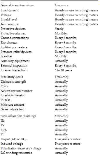
TABLE--7 Transformer Inspection and Maintenance Checklist General inspection
items Frequency Load current Hourly or use recording meters Voltage Hourly
or use recording meters Liquid level Hourly or use recording meters Temperature
Hourly or use recording meters Protective devices Yearly Protective alarms
Monthly Ground connections Every 6 months Tap changer Every 6 months Lightning
arresters Every 6 months Pressure-relief devices Every 3 months Breather
Monthly Auxiliary equipment Annually External inspection Every 6 months
Internal inspection 5 to 10 years Insulating liquid Frequency Dielectric
strength Annually Color Annually Neutralization number Annually Interfacial
tension Annually PF test Annually Moisture content Annually Gas-analysis
test Annually Solid insulation (winding) Frequency IR Annually PF Annually
FRA Annually PI Annually Hi-pot (AC or DC) Five years or more Induced voltage
Five years or more Polarization recovery voltage Annually DC winding resistance
Annually
====
Protective devices: Basic transformer protection is covered by the NEC. This protection is supplemented with additional protective relays and devices.
It is important that protective devices are inspected and maintained on a regular basis to ensure that these devices will operate in case of transformer malfunction or failure. The following protective devices along with other protective devices not listed here should be inspected and maintained on an annual basis.
Overcurrent phase and ground relays
Differential relays
Sudden pressure relays
Under- and overvoltage relays
Alarm and auxiliary relays
Wiring and current-transformer associated with the protective relays
Protective alarms: Transformers come with various types of alarms, such as overtemperature, liquid temperature, and pressure-relief devices. These are usually open-type contacts that can be connected to either alarm or trip the circuit breaker. The alarm contact and associated wiring should be inspected on a monthly basis.
Ground connections: The transformer tank is always solidly grounded to eliminate electric shock per the NEC. The grounding straps for transformer tanks should be checked for loose, broken, or corroded connections. The ground resistance of the substation will depend upon the type and size of the substation. The ground resistance may vary from less than 1 Ohm for large sized substations to 25 Ohm for very small-sized substations. The frequency of this inspection and test should be annual.
Lightning arrester: When transformers are supplied from overhead lines, lightning arresters are used to protect the transformer from lightning and other surges. Lightning arresters should be inspected for looseness, broken parts, dirt, and other deposits. All dirt and deposit should be cleaned, loose connections tightened, and broken parts replaced during this check. The inspection of the lightning arrestor and its grounding system should be done annually.
Pressure-relief device: Most sealed transformers are equipped with pres sure-relief devices to relieve excessive pressure in the tank due to the internal arcing. This device is set to open at a pressure of 10-15 psi. Routine inspection of pressure-relief devices should include checking for leaks around joints, diaphragm cracking, and the like. This inspection should be done quarterly.
Breather: Many transformers have breathers of either the open type or dehydrating type. The function of the dehydrating agent is to prevent moisture from entering the transformer tank. Most dehydrating breathers contain silica gel, which will change from blue when dry to pale pink when wet.
Inspection can be made through a glass window provided for the purpose.
The breathers should be checked monthly and the dehydrating agent replaced or reconditioned if found restrictive or wet.
Auxiliary equipment: Auxiliary equipment required for cooling, such as fans, oil pumps, control devices, and wiring, should be checked on an annual basis. The equipment should be cleaned and damaged parts replaced.
External inspection: The transformer should be given an external inspection on a semiannual basis. The inspection should include checking the tank, radiators, auxiliary equipment, gasket leakage, and metal parts for corrosion. Also, the electrical connection should be checked for tightness and overheating. Transformer bushings should be checked for mechanical damage, cleanness, and leakage. Bushings should be wiped clean on a regular basis to minimize flashovers.
Internal inspection: This inspection involves the internal investigation of the tank and core. On liquid-filled transformers, the covers can be removed to examine for evidence of moisture or rust around the bushing supports and transformer top cover. To examine the tank and core, the liquid can be drained out. Examination of the core should be made to check for sludge deposits, loose connections, and any damage to the transformer parts.
Evidence of carbon may indicate internal problems. The winding inspection should be checked for damage to terminal panels, barriers, loose connections, and overall connection of the winding. Obviously, such things as untanking the transformer for internal inspection would have to be judiciously made and would depend on the age of the transformer and its over loading and trouble history. The frequency of this inspection should be 5 to 10 years or more.
Transformer fluid: All transformer fluids are subject to deterioration, and the main contaminants are air, moisture, and heat. These contaminants react with transformer fluid and produce acids and sludge. The acid, in turn, attacks the winding insulation, and sludge deposits tend to decrease cooling. Moisture in the transformer fluid tends to lower the dielectric strength of the fluid, which combined with sludge, will lower the flashover value of insulators and terminal boards inside the transformer tank. As discussed earlier, regular inspection of the transformer is needed to maintain the fluid in a contaminant-free state. For proper maintenance of insulating fluids refer to Section 4.
7.3.5 Drying-Out Methods
Similar to dry-type transformers, the liquid insulating transformer can be considered as consisting of core and coil assembly, except that the assembly is immersed in an insulating fluid. Elaborate measures are taken to prevent and detect the infiltration and increase of moisture con tent in the transformer. Before the transformer liquid becomes saturated with water, the paper insulation of the winding in a transformer has already absorbed a concentration of moisture because of its great affinity for water. The water in the paper insulation accelerates the degradation of the insulation and lowers its electrical integrity.
We have discussed in the previous sections several tests to judge the dryness of the transformer, such as IR, PI, and PF. One simple method for detecting the water content in the transformer oil can be made by an approximate method known as the cloud test. It consists of cooling a test tube sample of oil in an ice bath. If a cloud appears in the test tube above 0°C, the transformer contains excessive moisture. Confirmation of the water content in the transformer can be made by a laboratory test.
The distribution of moisture in the transformer is always in a state of un-equilibrium. Through the cooler range of temperatures, the solid insulation of the transformer winding will tend to absorb more moisture than the transformer liquid. However, as the transformer is loaded, the rise in winding temperature will release this moisture. This change due to varying loads and temperature is constant, regardless of whether there is an excess of water or only a very small quantity of moisture in the transformer. Also, transformer liquids such as oil tend to hold more water with an increase in temperature. In other words, there will be more moisture in the transformer oil when it is carrying a load than when it is unloaded. Other factors, such as decomposition of paper insulation and contaminants, will tend to generate more moisture in the transformer liquid. When it becomes necessary to dry out liquid transformers, the following methods can be used: (1) heat alone, or (2) heat followed by vacuum.
Heat alone: This method involves application of heat to the transformer alone. One form of heat application is oven drying, which can be done at any of the service shops of major manufacturers. When the transformer is oven dried in the service shop, it is important to monitor the winding resistance to see when the transformer, reaches oven temperature (100°C-120°C). PF and IR measurements should be made at about 6 h intervals to see when drying is achieved, that is, when at least four readings are of the same value.
Heat followed by vacuum: The heating of the transformer with liquid can be performed by applying short circuit to the transformer or by circulating hot oil by means of an external system. As in the previous method, PF and IR measurement should be made at about 6 h intervals. Completed drying is indicated by at least four readings that are the same. The field drying methods may involve heating the transformer liquid, removing the liquid, and immediately applying high vacuum. Another method may involve removing the liquid and heating the transformer by circulation of hot air.
Once the winding reaches 90°C-100°C a high vacuum of about 0.5 Torr is applied. When the temperature drops below 50°C, drying is stopped. The normal length of time to apply heat and vacuum may be a week or more, depending on the size of the transformer. Once the transformer is dried and the vacuum pulled, clean transformer liquid can be introduced into the transformer. Precautions to observe during this process are as follows:
- Before the vacuum is pulled, make sure the tank is braced for full vacuum
- The air temperature for drying should not exceed 100°C
If new undried coils are used for replacement purposes, the coil clamps should be checked after drying is complete since shrinkage may occur during drying.
When drying is performed on an energized transformer, precautions should be taken to prevent formation of bubbles during the degassing phase.
Otherwise, immediate failure may occur.
The transformer liquid level should be carefully watched because unintentional lowering of transformer liquid level may cause a transformer failure.
7.3.6 Storage
Transformers should be stored in a safe, dry, ventilated location with uniform temperature. In locations where no controls for uniform temperature exist, condensation and absorption of water can be minimized by installation of space heaters or incandescent lamps.
Because of new regulations on the use, disposal, and storage of askarel, transformers using askarel as an insulating liquid will require special storage facilities. The reader is urged to consult regulations put out by the EPA.
7.3.7 Transformer Diagnostic Guide
For troubleshooting purposes, a diagnostic guide and causes of transformer failures (TABLE--8) are provided. This information is by no means complete, and the reader is urged to check and test for the problem and its cause. Refer to Section 1.8.2 for failure modes of transformers. In general, the following conditions will cause the troubles indicated:
Overtemperature: Overtemperature can be caused by an overcurrent, over voltage, insufficient cooling, low liquid level, sludge in the transformer liquid, high ambient, or short-circuited core. In dry-type transformers, this condition can be due to clogged ducts.
Winding insulation failure: This is an electrical fault in the transformer winding insulation where it can involve phase-to-ground, phase-to-phase, three-phase and/or ground, or turn-to-turn-type short circuit. The causes for this type of failure may be due to a short-circuit fault, lightning, overload or overcurrent condition, or transformer liquid containing moisture and contaminants.
Incorrect secondary voltage: This condition can be due to improper turns ratio, abnormal primary voltage, and/or shorted turns in the transformer.
Bushing failure: Bushing failure can be caused by flashover due to dirt accumulation and/or lightning strikes.
Internal arcing: Internal arcing can be caused by low liquid level exposing live parts of the transformer, loose connections, or failure of the transformer dielectric. Usually, internal arcing can become audible and cause radio interference.
Core failure: This condition is due to the failure of core laminations, core, bolts, clamps, and so on.
=======
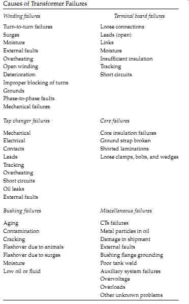
TABLE--8: Causes of Transformer Failures
Winding failures Terminal board failures Turn-to-turn failures Loose connections Surges Leads (open) Moisture Links External faults Moisture Overheating Insufficient insulation Open winding Tracking Deterioration Short circuits Improper blocking of turns Grounds Phase-to-phase faults Mechanical failures Tap changer failures Core failures Mechanical Core insulation failures Electrical Ground strap broken Contacts Shorted laminations Leads Loose clamps, bolts, and wedges Tracking Overheating Short circuits Oil leaks External faults Bushing failures Miscellaneous failures Aging CTs failures Contamination Metal particles in oil Cracking Damage in shipment Flashover due to animals External faults Flashover due to surges Bushing flange grounding Moisture Poor tank weld Low oil or fluid Auxiliary system failures Overvoltage Overloads Other unknown problems
=======
High exciting current: Usually, high exciting currents are due to short circuited core and/or open core joints.
Low dielectric strength: This condition can be caused by condensation and penetration of moisture due to improper ventilation, broken relief diaphragm, leaks around transformer accessories, or cooling coil leakage.
Oxidation of oil: Oxidation usually results in the formation of acids and sludge in the transformer liquid. It is mainly due to exposure to air and high operating temperatures.
Pressure-relief diaphragm broken: This is due to an internal fault causing excessive internal pressures or the transformer liquid level being too high or excessive internal pressure due to loading of transformer.
Discoloration of transformer liquid: Discoloration is mainly caused by carbonization of the liquid due to switching, core failure, or contaminations.
Leakage of transformer liquid: Leakage can occur through screw joints, around gaskets, welds, casting, pressure-relief device, and so on. The main causes are improper assembly of mechanical parts, improper filters, poor joints, improper finishing of surfaces, defects in the material used, or insufficient tightness of mechanical parts.
Moisture condensation: The main causes for moisture condensation are improper ventilation in open-type transformers and a cracked diaphragm or leaking gaskets in sealed-type transformer.
Gas-sealed transformer troubles: In gas-sealed transformers, additional problems can be the loss of gas, oxygen content above 5%, or gas regulator mal functions. These problems are caused by gas leaks above the oil, leaky valve seats, insufficient gas space, and/or insufficient flushing of gas space with nitrogen.
Transformer switching equipment troubles: Many transformers are equipped with tap chargers and other switching equipment. The problems associated with these transformers may be excessive wearing of contacts, mechanism overtravel, moisture condensation in mechanism liquid, and others. Excessive contact wear is due to loss of contact pressure from weakened springs or a contact-making voltmeter set at too narrow a bandwidth or insufficient time delay. Mechanism over-travel usually is due to defective or improper adjustment of controller contacts. Moisture condensation is due to improper ventilation, and carbonization is due to excessive operation and lack of filtering. Other problems such as control fuse blowing and mechanism motor stalling are due to short circuits in the control circuit, mechanical binding, or low-voltage conditions in the control circuitry.