AMAZON multi-meters discounts AMAZON oscilloscope discounts
5. Transformer Polarity, Terminal Markings, and Connections
5.1 Single-Phase Transformers
Primary and secondary terminals of a single-phase transformer have the same polarity when the current enters the primary terminal and at the same time leaves the secondary terminal. Transformers are constructed with subtractive and additive polarities.
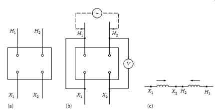 FIG. 8 (a) Subtractive polarity of single-phase transformer, (b) connection
for polarity test, and (c) resultant voltage across H1 and X1.
FIG. 8 (a) Subtractive polarity of single-phase transformer, (b) connection
for polarity test, and (c) resultant voltage across H1 and X1.
5.1.1 Subtractive Polarity
When the high-side lead, H1 and low-side lead, X1, are brought out on the same side of the transformer, the polarity is said to be subtractive, as shown in FIG. 8a. If leads H1 and X1 are connected and the high side is energized with a given voltage, the resulting voltage, which appears across the H2 and X2 leads, will be less than the applied voltage (see FIG. 8b). This is due to the fact that in this series connection the low-voltage winding opposes the high-voltage (HV) winding, and thus the low voltage is subtracted from the HV (see FIG. 8c).
5.1.2 Additive Polarity
When the high-side lead, H1, and low-side lead, X2, are brought out on the same side of the transformer, the polarity is said to be additive. If the leads H1 and X2 are connected and a given voltage is applied to the high side, the resultant voltage across the H2 and X1 leads is the sum of the high- and low voltage windings. Additive polarity is shown in FIG. 9.
In general, polarity is not indicative of a higher or lower arrangement of potential stresses within a transformer or arrangement of windings. Both sub tractive and additive polarities are found in transformers. Additive polarity is more prevalent in distribution-type transformers and subtractive polarity in power transformers.
The connections of single-phase distribution transformers usually have their windings divided into two or more sections. When the two secondary windings are connected in parallel, their currents add, and if the two windings are connected in series, their voltages add. The connection output is the same in both cases: for example, for series connection each secondary winding rated at 115 V and 100 A, therefore the output is equal to 230 × 100 = 23,000 VA or 23 kVA; and for parallel connection it is equal to 115 × 200 = 23,000 VA or 23 kVA. These connections are shown in FIG. 10.
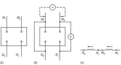
FIG. 9 (a) Additive polarity of single-phase transformer, (b) connection
for polarity test, and (c) resultant voltage across H1 and X2.
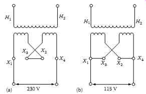
FIG. 10 Single-phase transformer connections: (a) series connections
and (b) parallel connections.
5.2 Three-Phase Transformers
The polarity of three-phase transformers is fixed by the connections between phases, as well as by the relative locations of leads, and can be designated by a sketch showing lead markings and a vector diagram showing the electrical angular shift between terminals. The basic three-phase transformer configurations are as follows:
Delta-delta; Wye-wye (star-star); Delta-wye (star) Wye (star)-delta
These connections are shown in FIG. 11. The standard angular displacement between reference phases of a delta-delta bank or a star-star bank is 0°. The standard angular displacement between reference phases of a star-delta or a delta-star bank is 30°. The American National Standards Institute (ANSI) standard C57.12 stipulates that for such three-phase banks the HV reference phase angle is 30° ahead of the reference low voltage, regardless of whether the bank connections are star-delta or delta-star.
The lead marking of three-phase transformers has been standardized by ANSI and NEMA for the purpose of paralleling operation. The HV lead H1 is brought out on the right side when facing the HV side of the transformer case. The remaining HV side leads H2 and H3 are brought out and numbered in sequence from right to left. The low-voltage side lead, X1 is brought out on the left side facing the low side of the transformer case. The remaining low-voltage side leads, X2 and X3, are numbered in sequence from left to right. This is shown in FIG. 12.
The four basic three-phase transformer configurations can be accomplished by connecting three single-phase transformers or by connecting three-phase windings within one tank. All the configurations provide symmetrical connections. The relationship between each phase for high- and low-side voltage is 120°, as shown in the vector diagrams of FIG. 13a and b. There are many other connections that give different phase displacement, and the reader is urged to review a text on transformer connections.
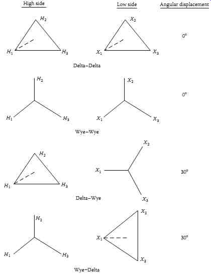
FIG. 11 Three-phase connection and angular displacement. High side Low
side Angular displacement; Connections: Delta-Delta; Delta-Wye; Wye Wye;
Wye Delta
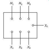
FIG. 12 Three-phase transformer terminal marking.
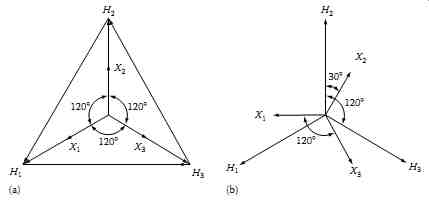
FIG. 13 Phasor relationship of high- and low-side voltages: (a) delta-delta
or wye-wye connection; (b) delta-wye or wye-delta connection.
For parallel operation of single- or three-phase transformers, it is essential that certain conditions be maintained. For example, when placing single phase transformers in parallel, it is important to have the same voltage ratios and impedances. Similarly, the like polarities of each transformer must be connected together when placing single-phase transformers in parallel. One should be very careful in paralleling transformers, because many problems can arise if proper consideration is not given to the transformer connections and characteristics. Some of the problems in paralleling transformers that require careful analysis are the following:
Paralleling transformers having different winding connections Transformers with different impedances or turns ratio or different primary voltages Transformers of different polarity and phase displacement The reader is urged to consult a transformer text before paralleling transformers.
6. Transformer Characteristics
Most transformers used in industrial and commercial facilities range from 500 to 2500 kVA and are three-phase, liquid-filled or dry type located indoors.
These transformers are part of secondary unit substations supplying service to load centers. Transformers used for the distribution of power in plants and buildings have similar characteristics, which have been standardized as follows:
kVA rating: The rating must be adequate to carry the connected load.
Voltage ratings: The voltage rating provides the primary and secondary volt age to transform electrical energy from primary voltage to secondary voltage.
This rating is associated with the winding turns ratios of the primary and secondary windings. Some examples of standard voltage ratings for power transformers are shown in TABLE--1.
Cooling: The type of cooling determines the method of medium used to dissipate heat generated in the transformer. Transformer kVA rating is specified based upon the temperature rise allowed for a given transformer.
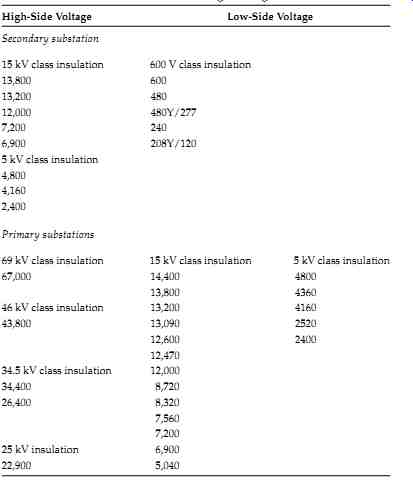
TABLE--1 Three-Phase Transformer Standard Voltage Ratings: High-Side
Voltage; Low-Side Voltage Secondary substation
Primary substations: 69 kV class insulation; 15 kV class insulation; 5 kV class insulation
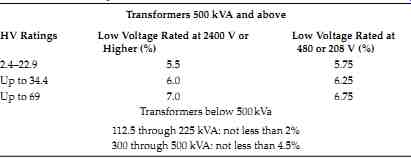 TABLE--2 NEMA Standard Impedance Values for Transformers
Transformers 500 kVA and above
Insulation class: The insulation class of a transformer is based upon the nominal voltage levels at which the system voltages and currents are transformed. For example, the ANSI standard C57.12 secondary and primary substation voltage ratings are listed in TABLE--1 for the various insulation-class levels.
Impedance level: The impedance of a transformer can be expressed as an impedance drop expressed in percent. This is equal to impedance drop voltage expressed as a percentage of rated terminal voltage. For most power transformers, the impedance can be considered equal to the reactance since the resistance component is very small. The NEMA has standardized the impedance values for transformers that are built in accordance with NEMA standards, which are shown in TABLE--2.
Short-circuit conditions: The ANSI standard C57.12 defines the short-circuit withstand capability of a transformer as the ability to withstand without- injury short circuits on any external terminals, with rated line voltagesmaintained on all terminals intended for connection to sources of power.
Symmetrical Current Time (s)
- 25 rated current 2
- 20 rated current 3
- 16.6 rated current 4
- 14.3 rated current 5
The duration and values of short circuit are limited by ANSI as follows:
Voltage taps: Many power transformers for industrial applications are equipped with voltage ratio tap changers. The tap changer is used to maintain a constant secondary voltage with variable primary voltage or to control the secondary voltage with a fixed primary voltage. Usually, most transformers will have two 5% taps or four 2.5% taps on the HV side for adjustment to maintain constant secondary voltage.
Sound level: All transformers hum and create noise when they are energized. This noise is generated by vibrations in the laminated core, and the noise frequency is double the fundamental frequency. The noise level of transformers should be considered during installation in order not to exceed Occupational Safety and Health Administration (OSHA) regulations. Typical ratings for distribution transformers are listed as follows:
Basic impulse insulation level (BIL): BIL is the crest value of the impulse voltage that the transformer is required to withstand without failure. The transformer BIL impulse duration is 1.2 × 50 µs. That is, the impulse reaches its peak value in 1.2 µs and then decays to 50% of its peak value in 50 µs.
In addition to full BIL value, transformers are tested for chopped-wave with stand (115% of BIL) and front-of-the-wave withstand (160% of BIL). These tests are intended to simulate conditions that can occur when transformers are subjected to lightning surges.