AMAZON multi-meters discounts AMAZON oscilloscope discounts
<<<Cont. from Part 1
3. Applications of Motors and Generators
Motors and generators are applied on the basis that they can carry the rated load and withstand the environmental conditions during their rated life reliably. Because of the different requirements of various industries for motors, each industry has over the years developed different application criteria for motors. Therefore, a wide variety of motor insulation and construction classes are available (manufactured in accordance with NEMA MG1 standards) to satisfy these needs. The actual life and reliability of motors are determined by combining the experience of industry requirements and electrical characteristics. The reliability of a machine can be defined in terms of its electrical and mechanical integrity, which are explained next.
3.1 Electrical Integrity
The electrical integrity of a machine can be stated in terms of the dielectric and load-time ratings.
3.1.1 Dielectric Rating
Dielectric rating can be defined as the ability to correctly maintain the separation of the conducting and nonconducting parts from the power system supply voltage. To achieve the required dielectric integrity, various insulation systems are used, depending on the type of motor and service conditions.
Most equipment manufacturers have standardized on roughly the same set of dielectric strengths for their insulation systems given the operating conditions most frequently encountered, and the requirements of NEMA.

FIG 4 (a) Wye-connected dual voltage and (b) delta-connected dual voltage.
For installations where commercial or industrial power sources are used, the established practices have worked very well. Recently, with the introduction of variable frequency induction motor drives using pulse width modulated (PWM) switching technology, some standard 600 V class machines have experienced insulation failures. The reasons for such failures must be evaluated on case by case basis; however, the most common problem results from failure to consider the drives' modulating frequency and the length of the motor leads between the drive's output terminals and the motor itself.
At frequencies in the several kilohertz to tens of kilohertz range, the supply cables to the motor no longer act as simple conductors as they do at 60 Hz.
If the cables are too long, they tend to act as incorrectly tuned transmission lines, which lead to a significant reflected voltage wave each time the current is switched. This buildup tends to concentrate at the first few turns of the motor winding. Manufacturers are approaching these applications in several ways: (1) by specifying the maximum lead length for a given horsepower, voltage and modulating frequency and using a standard, NEMA design motor; (2) by applying snubber/RC-filter assemblies at key locations and keeping the standard, NEMA design motor; (3) by offering motors for PWM service whose dielectric designs have been enhanced in order to withstand the additional electrical stress produced by the PWM sources. In cases where the motor and drive are supplied by different manufacturers, each should be given the full nameplate information of the motor, the approximate length of cable between the controller and the motor, and the nature of the load to be driven. This will allow one or both suppliers to offer components that will work as a coordinated system.
3.1.2 Load-Time Rating
The load rating relates to the ability of the machine to carry a load over a period of time. Load ratings can be classified as service-factor duty, short-time duty, and overload duty.
Service-factor duty is defined as the multiplier that is multiplied by the nameplate horsepower; the result is used for temperature testing with continuously applied load until the temperature equilibrium is reached.
For example, a service factor of 1.0 means that the motor cannot carry an overload on a sustained basis without exceeding the insulation temperature.
A service factor of 1.15 has been established as a standard for open and drip-proof general-purpose motors below 200 hp. Larger motors have a service factor of 1.0. A service factor of 1.15 usually translates into a 10°C higher temperature with 15% overload.
Short-time duty is defined by a motor operating at continuous load over a period of time less than that required to reach thermal equilibrium.
The short-time duty ratings are usually 15, 30, or 60 min. Motors should be allowed to cool down to ambient temperature when they are operated in this manner before the next load cycle is applied; otherwise, the motor will overheat.
Overload duty is defined as the ability of the motor to continuously carry an overload for an extended period of time. A common rating is an overload of 25% for 2 h. It is expected that the motor will not reach thermal equilibrium for the time specified for the overload rating.
3.2 Mechanical Integrity
Mechanical integrity involves mechanical stresses, vibrational forces, and the ability to keep moving parts separate from stationary parts. The mechanical stresses imposed on motors are due to motor torques and loads. Motors that are switched frequently are more susceptible to these stresses. Vibrations are a result of incorrect alignment, incorrect mounting, and incorrect installation, which will tend to deteriorate the motor life performance.
However, the most critical mechanical part of the motor is the bearings, where stationary and rotating parts meet. To ensure optimum performance, the bearings should be correctly matched to the load, kept clean, lubricated, and aligned correctly. Motor bearings include babbitted, sleeve, and ball types. The fatigue life of ball bearings varies inversely with the cube of the load. The load usually imposes a side force on the shaft extension owing to driven-equipment connections such as belts, gears, or chains. The fatigue life of sleeve bearings is infinite due to the fact that the oil film supports the shaft; and if maintained correctly, they will last indefinitely.
Motors and generators conforming to NEMA standards are designed to operate in accordance with ratings under the usual service conditions as listed in NEMA MG1 standards. Motors and generators operated under service conditions other than those specified in NEMA MG1 standards, may involve some hazard. The severity of this hazard depends upon the degree of departure from the usual conditions. Hazards usually result from overheating, abnormal deterioration of the insulation, mechanical failure, corrosion, and fire. Therefore, the manufacturer should be consulted for further information concerning the usual service conditions.
4. AC Motors
Criteria used as guidelines for the application of AC motors are discussed next.
4.1 Environmental Conditions
The usual service conditions that a motor is exposed to are the following:
Ambient temperature not to exceed 40°C and areas with adequate ventilation
Altitude not to exceed 3300 ft
Machine installed on a rigid mounting and with belt, chain, or gear drive
Unusual service conditions for motor operation or exposure can be listed as the following:
Combustible, explosive, abrasive, or conducting dust
Excessively dirty operating conditions where accumulation of dirt will interfere with motor ventilation
Chemical fumes and explosive or flammable gases
Abnormal shock, vibration, or mechanical loading from external sources
High humidity areas, oil vapors, steam, or salt-laden air
Excessive departure from rated voltage, frequency, or both
Supply voltage is unbalanced
Operation above rated speed
Poor ventilation
4.2 Direction of Rotation
Synchronous, universal, single-phase, and nonreversing DC motors have counterclockwise rotation when facing the end of the machine opposite the drive. For AC and DC generators, the rotation is clockwise.
4.3 Operation at Altitudes above 3300 ft
The temperature rises for motors and generators are based on a maximum altitude of 3300 ft with a maximum ambient temperature of 40°C. Motors and generators having a Class A or B insulation system will operate satisfactorily at altitudes above 3300 ft with ambient temperatures as shown in TBL. 2.
4.4 Voltage and Frequency
General-purpose induction and synchronous motors are designed for a rated voltage, frequency, and number of phases. The supply voltage must be known in order to select the correct motor. For AC motors, the motor nameplate voltage will normally be less than the nominal power system voltage, as shown in TBL. 3 for three-phase 60 Hz motors.
TBL. 2 Ambient Temperature versus Altitude Ambient Temperature (°C) Maximum Altitude (ft) 40 3300 30 6600 20 9900
TBL. 3 Motor Voltage Ratings Nominal Power System Voltage (V) Motor Utilization (Nameplate), Voltage (V)
Voltage and frequency variations:
•When the voltage at the terminals of a motor varies from nameplate rating, the performance or life of the equipment may be sacrificed. The effect may be serious or minor depending upon the amount the voltage deviates from the nameplate rating. NEMA standards provide a ±10% tolerance from the nameplate rating for operation of induction general-purpose motors. However, even small deviations of voltage from nameplate ratings have an effect on the performance of the motor. The following are some of operating results caused by variations of frequency and voltage.
High voltage on induction motor: The most significant effects of too high a voltage are increased torque, starting current, and heat, and decreased power factor (PF).
Low voltage on induction motor: The most significant effects of too low a voltage are reduced starting torque, increased PF, and increased heating.
The increased heating at low voltage and full load reduces the life of the insulation system of the motor.
High and low frequency of induction motor: An increased frequency of the induction motor above the rated frequency will usually improve the PF, decrease locked rotor torque, and increase the speed, friction, and wind age loss. A decreased frequency below nameplate rating will have the opposite effects. When variations of frequency and voltage occur at the same time, the effects are superimposed. NEMA standards allow a combined voltage and frequency deviation of ±10%.
Voltage unbalance: The voltage supplied to the motor should be equal because voltage unbalance will produce circulating negative sequence currents, which in turn produce heating in the motor. Two to three percent unbalance voltages to the motor will produce the same heating as a 10% overload on the motor. A motor should be derated when the unbalance reaches 4%.
4.5 Horsepower, Torque, and Speed Considerations
The horsepower of a motor can be defined as the capability of the motor to do a given amount of work. Motors are rated as fractional or integral horsepower. The torque of a motor can be defined as the turning force developed by the motor, or it can be referred to as the resistance offered to the turning force by the driven load. Usually, torque for motors is expressed in terms of percentage of rated full-load torque. The speed of the motor is expressed as rpm, that is, a rate of measure of motion. The several definitive speed terms (as outlined in the section on the classification of motors according to variability of speed) that are common to all motors are standardized in order to relate the delivery of torque at a given speed for purposes of application. For AC motors the synchronous speed can be calculated as { } Synchronous speed (Ns) 120 frequency/(no. of poles) =× Induction motors, however, operate at actual speeds that are less than the synchronous speed because of losses in the motor. The difference between synchronous and actual speed is knows as slip. Slip is usually expressed as a percentage of synchronous speed and can be calculated as
Slip (%) {Synchronous rpm actual rpm 100} /{Synchronous rpm}
=-×
The horsepower of the motor can be stated in mechanical or electrical terms.
One horsepower (1 hp) is equal to 33,000 ft. lb/min. The torque produced by an electric motor can be calculated as
Torque {5252 hp}/{actual speed} =×
Also:
Horsepower (hp) Watts/746 kW/0.746
{torque actual speed}/{5252}
A typical torque-speed curve for a motor is shown in FIG 5. The various NEMA design motor torque-speed curves are shown in FIG 6.
In order to apply motors, the first thing to determine is the desired full load speed and the desired horsepower at that speed. Other factors required when applying motors are type of torque required by the load and the starting current limitations. Motor torque characteristics must match those of the load from starting to the time when the motor reaches its rated speed.
The motor must develop net accelerating torque for every point on the load curve in order to reach its actual speed.
===
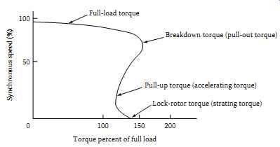
FIG 5 Typical torque-speed curve.
100 Full-load torque Breakdown torque (pull-out torque) Pull-up torque (accelerating torque) Lock-rotor torque (starting torque) 50 Synchronous speed (%) 0 100 150 Torque percent of full load 200
===
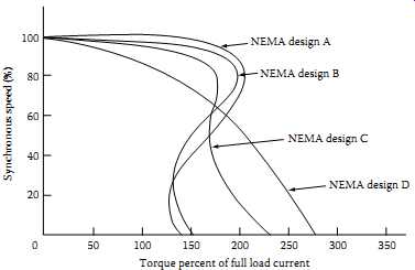
FIG 6 NEMA design motors torque-speed curves.
NEMA design A NEMA design B NEMA design C NEMA design D Synchronous speed (%) Torque percent of full load current 350 300 250 200 150 100 50 0 20 40 60 80 100
===
To understand the torques developed by the various motors, the following definitions are given; they are shown in FIG 5 for each design type of motor.
Lock-rotor torque (starting torque):
•The minimum torque developed by the motor for all angular positions of the rotor when the primary winding (stator winding) is energized with AC power supply.
Accelerating torque:
•The torque developed with rated power input during the period from standstill to full speed. This is the net positive torque available to the motor beyond the torque required by the load.
Breakdown torque (maximum torque):
•The maximum torque developed by the motor at rated power input without an abrupt change in speed.
Pull-out torque:
•The maximum torque developed by a motor for 1 min without stalling. It is frequently referred to as the breakdown torque.
Pull-in torque:
•The torque developed during the transition from rated speed (slip speed) to synchronous speed.
Pull-up torque:
•The minimum torque developed with rated power input during the period of acceleration from standstill to rated speed.
Full-load torque:
•The torque developed at rated speed with rated power input.
Torque characteristics of various motors can best be described by comparing one motor type with another. Torques are classified as very high, high, medium, low, and very low. The torque-speed curves for the various NEMA motor designs as listed under classification according to application shown in FIG 6.
4.6 Power Factor
The connected motor load in a facility is usually a major factor in determining the system PF. Low system PF results in increased losses in the distribution system. Induction motors inherently cause a lagging system PF and, under certain circumstances, they can cause a very low system PF.
The PF of an induction motor decreases as the load decreases. When the load on the motor is increased, the rated load PF increases; that is, a fully loaded motor has a higher PF. Several induction motors, all operating at light load, can cause the electrical system to have a low PF. The PF of induction motors at rated load is less for low-speed than for high-speed motors.
A small increase in voltage (10%) above rated voltage will decrease the PF, and a small decrease in voltage (10%) below rated voltage will improve the PF of an induction motor. However, other performance characteristics may be adversely affected by such a change in voltage. Therefore, operation as close as possible to the nameplate voltage and horsepower ratings is recommended.
The PF of synchronous motors can range from 1.0 to approximately 0 PF leading, depending on the rated PF and the load for which they are built.
Standard designs are usually rated for unity, 0.8 lagging, or 0.8 leading PF. As previously stated, synchronous motors have the capability of improving the PF of the electrical system.
4.7 Motor Selection
Induction motor: The selection of the induction motor depends on the performance characteristics of the driven machine, and these, in turn, determine the operating characteristics of the motor. Some machines, such as most fans, blowers, centrifugal pumps, and unloaded compressors, require a relatively low starting torque. After starting, the required driving torque increases with increasing speed up to the full-load speed and torque. A design B motor is frequently selected to drive this type of application.
Other machines, such as reciprocating air compressors and loaded conveyors, require high starting torque. The torque needed to start the machine is sometimes greater than the torque required at full-load speed.
A design C motor is frequently selected to drive this type of application. For driven machines that impose pulsating loads or require frequent starting of the motor, such as punch press and well pumping, and hoist applications, a design D is often used.
Synchronous motors: In general, large synchronous motors can be applied to any load that induction motors with design B or C characteristics can handle.
They have a higher efficiency than an induction motor of the equivalent rating and are capable of improving the system PF. When efficiency is a primary consideration in choosing a relatively large motor, a 1.0 PF synchro nous motor may provide the solution. Where system PF improvement is a primary consideration, the use of a 0.8 leading PF synchronous motor may provide the solution.
Multispeed motors: Multispeed motors can be designed to have speed-torque characteristics similar to those of design A, B, C, or D motors of the equivalent rating. They can be designed for variable torque, constant torque, or constant horsepower. For the highest efficiency, it is important to select the correct multispeed motor characteristic for the load at all operating speeds.
Typical examples of variable-torque loads are fans and centrifugal pumps.
Constant-torque motors are used to drive apparatus such as conveyors, positive displacement pumps, and compressors. Machine tools and winches are examples of drives requiring the use of constant-horsepower motors.
5 AC Generators
Application criteria for AC generators are discussed next.
5.1 Service Conditions
AC generators, like AC motors, should be correctly selected with respect to their service conditions. The usual and unusual conditions are the same for genera tor applications as those listed for AC motors. Some generators may operate in accordance with their ratings under one or more unusual service conditions.
However, where some unusual service condition exists, a special-purpose generator may be required. Even though in such cases past experience may be the best guide in selecting the machine, it is recommended that the manufacturer be consulted concerning the mechanical and thermal duty of the machine.
5.2 Ratings
The continuous basis of rating synchronous generators is in kilowatts (kW) or kilovolt-amperes (kVA) at 80% PF. The ratings of kVA, speed, voltage, frequency, and so on, are expressed in NEMA MG1 standards for three-phase and single-phase machines. The excitation voltages for the field windings are also stated in the same NEMA standards; they are 62.5, 125, 375, and 500 V DC. These excitation voltages apply to machines with brushes only.
Synchronous generators are capable of carrying a 1 min overload of 50% of normal rated current with the field set at normal rated load excitation. A synchronous generator is designed to withstand three-phase short-circuit cur rent at its terminal for 30 s operating at rated kVA and PF, at 5% overvoltage with fixed excitation. The phase current due to faults other than three-phase faults must be limited by external means to a value that does not exceed the maximum phase currents obtained from three-phase fault.
The kW output of the machine depends upon the voltage, armature cur rent, and PF. Also, the synchronous generator kVA ratings may be stated at definite voltage and frequency. The permissible load output of the synchro nous generator depends upon the balance of the load. It is maximum for balanced loads and minimum for single-phase loads.
TBL. 4 Temperature Rise for Synchronous Generators
5.3 Temperature Rise
The temperature rise under rated load conditions for synchronous generators is based on the insulation system used for the machines. The temperature rise is determined in accordance with the latest IEEE std 115-1995, IEEE guide: Test Procedures for Synchronous Machines. The method of temperature determination may be resistance or embedded resistance temperature detector (RTD). TBL. 4 lists the various temperature rises for the various generator sizes and insulation systems.
The standard ambient temperature is taken as 40°C, and where the ambient temperature is higher than the standard, it is recommended that the temperature rise of generators be reduced as follows:
For increases in ambient temperature above 40°C up to and including 50°C, decrease the temperature rise by 10°C For increases in ambient temperature above 50°C up to and including 60°C, decrease the temperature rise by 20°C
5.4 Variation in Voltage
Synchronous generators can operate at rated kVA, frequency, and PF at voltages above and below the rated voltage not to exceed 5%. The maximum voltage any synchronous generator can produce at a definite frequency depends upon the permissible pole flux and field heating. To maintain a rated voltage output, specific field excitation is necessary at some specified load and PF.
5.5 Regulation
Regulation of a synchronous generator at any given PF is defined as a percentage rise in voltage, a constant frequency at excitation, when rated kVA load is removed. The regulation depends upon armature reactance, armature effective resistance, change in leakage flux with change in load, and armature reaction.
6. DC Motors
Application criteria for DC motors are discussed next.
6.1 Service Conditions
Similar to AC motors, the DC motors should be selected with regard to their environmental conditions. The service conditions may be usual or unusual and may involve environmental as well as operating conditions. The service conditions listed for AC motors also apply to the application of DC motors.
6.2 Operation of DC Motor on Rectified AC
The performance of a DC motor operating on rectified AC is different than if it were operating on a DC source having the same effective value of voltage.
The reason for this is due to the continuous ripple or pulsation of the output voltage from the rectified AC voltage source. The ripple effect appears in the motor armature current and thus affects its performance. The effect of the rectified voltage on the motor armature current becomes significant when the rectifier pulse number is less than 6 or the amount of phase control is more than 15%. Also, when a DC motor is operated from an unfiltered rectifier power supply, bearing currents may result. Ripple currents may flow to ground by means of capacitive coupling between rotor winding and core.
Even though these currents are small in magnitude, they may cause damage to antifriction and sleeve bearings under certain circumstances. Measures should be taken to minimize these currents to avoid damage to the motor.
6.3 Operation of the DC Motor below Base Speed
When a DC motor is operated below base speed by means of reduced armature voltage, the motor will heat up if rated full-load torque is maintained. To avoid overheating of the motor, reduce the load to compensate for the overheating of the motor. The speed of the DC motor is directly proportional to the armature voltage, and the torque is directly proportional to the armature current. Overheating can result due to the insufficient heat dissipating ability of the motor at these speeds.
6.4 Operation of the DC Motor above Base Speed
DC motors are built so that in case of an emergency they can withstand an overspeed of 25% above rated full-load speed without mechanical injury.
6.5 Overload Capability
The general industrial motors of open, forced ventilation, and totally enclosed water-air-cooled types are capable of carrying, with successful commutation, 115% of rated horsepower load continuously at rated voltage through out their speed range. Refer to NEMA standard MG1, Sections 23.10, 23.11, and 23.28 for overload capability, momentary load capability, and rate of change of load current, respectively, on these types of motors.
7. DC Generators
Application criteria for DC generators are discussed next.
7.1 Service Conditions
The DC generators should be correctly selected with respect to their service conditions. These conditions may be usual or unusual, involving environmental and operating conditions. The typical service conditions that have been listed under Section 10.4 also apply to DC generators.
The DC generators are classified into industrial DC and other DC integral horsepower generators and large-apparatus DC generators (larger than 0.6 kW/rpm) of open type. The industrial generator ratings range from 0.75 to 720 kW, speeds range from 720 to 3450 rpm, and voltages range from 125 to 500 V. The large-apparatus DC generator ratings range from 125 to 6400 kW, speeds range from 200 to 900 rpm, and voltages range from 250 to 700 V. Refer to NEMA standards MG1, Section II, Part 15 and MG1, Section III, Part 24 for specific information on generator size, speed, and voltage ratings.
7.3 Temperature Rise
The temperature rise of DC generators under rated load conditions is dependent on the type of insulation system and enclosure used for the various parts of the machine. Either the thermometer or the resistance method is used for the measurement of temperature rise. Refer to NEMA standards MG1, Section II, Part 15 and MG1, Section III, Part 24 for specific information on temperature rise for the two types of generators.
7.4 Overload Capability
Industrial-type generators are capable of carrying overload for 1 min, with successful commutation loads of 150% of the continuous rated load amperes at rated load excitation. Large-apparatus DC generators of open type are capable of carrying 115% of rated current for 2 h and 200% of rated current for 1 min at rated speed and rated or less than rated voltage.
7.5 Voltage Excitation
Large-apparatus DC generators, when operated at less than rated voltage, shall carry currents equal to those corresponding to their kilowatt and voltage ratings. The load voltage at rated load of a self-excited, flat, compound-wound, drip-proof industrial generator, rated at 50 kW and smaller and employing class B insulation, shall not exceed 112% of the rated voltage at rated load.
7.6 Overspeed
DC generators are constructed so that, in an emergency, they will withstand overspeed of 25% without mechanical injury.
8. Motor and Generator Insulation Systems
8.1 Machine Insulation System
Insulation is obviously a limiting factor in the design of an electrical machine.
If the thickness of the insulation is increased, the space available for the current carrying conductor is reduced and the conduction of heat from the conductor to the iron is restricted. Requirements of an insulation system for machine stator windings are
1. High dielectric strength
2. High resistance to partial discharges (PD)
3. High thermal conductivity
4. Good resistance to abrasions
5. Good resistance to tape separation caused by thermal heating
6. Good resistance to moisture and oil vapor
Machine insulation system is made up of five major insulation subsystems as discussed below.
Turn-to-turn insulation system: Turn-to-turn insulation is located between separate wires in each coil. This is usually in the form of an enamel coating on the wire. Glass over enamel is used on severe applications both for formed and random-wound coils.
Phase-to-phase insulation system: Phase-to-phase insulation is located between adjacent coils in different phase groups.
Phase-to-ground insulation system: Phase-to-ground insulation is located between windings, as well as between windings and the ground or structural parts of the motor. A sheet material such as the liner used in stator slots provides both dielectric and mechanical protection.
Slot wedge insulation system: Slot wedge which holds conductors firmly in the slots is referred to as slot wedge insulation.
Impregnation insulation system: Impregnation is used to bind all of the other components together and to fill in the air spaces. A total impregnation applied in a fluid form and hardened, provides protection against contaminants.
The various insulation systems that make up the machine insulation system are shown in FIG 7. Refer to Section 1.7 in section 1 for additional information on insulating materials used for electrical equipment. The insulation systems used for machine windings are classified by NEMA and are listed below:
Class O: This insulation is rated for a total temperature of 100°C. It is made of materials or combinations of materials such as cotton, silk, and paper without impregnation.
Class A: This insulation is rated for a total temperature of 105°C. It is made of materials or combinations of materials such as cotton, silk, and paper when suitably impregnated or coated or when immersed in a dielectric liquid such as oil.
Class B: This insulation is rated for a total temperature of 130°C. It is made of materials or combinations of materials such as mica, glass fiber, asbestos, etc., with suitable bonding substances capable of operation at 130°C.
Class F: This insulation is rated for a total temperature of 155°C. It is made of materials or combinations of materials such as mica, glass fiber, asbestos, etc., with suitable bonding substances capable of operation at 155°C.
Class H: This insulation is rated for a total temperature of 180°C. It is made of materials or combinations of materials such as silicone elastomer, mica, glass fiber, asbestos, etc., with suitable bonding sub stances such as appropriate silicone resins and other materials capable of operation at 180°C.
Class C: This insulation is rated for a total temperature of 220°C. It is made of materials or combinations of materials such as Tel on and other natural or synthetic materials capable of operation at 220°C.
The industry standards, such as IEEE standards 112 and NEMA MG1 describe methods of temperature-rise measurements in rotating machinery. They are (1) measurements by thermometer and (2) resistance methods. Briefly, the resistance method is based upon the ambient and the total temperature rise, which is shown in FIG 8b. The thermometer method is based on four factors: (1) the standard ambient temperature of 40°C, (2) a service factor, (3) the measured temperature rise, and (4) the allowable hot spot. This is shown in FIG 8a. The various insulation systems normally used for machines are shown in TBL. 5.
===
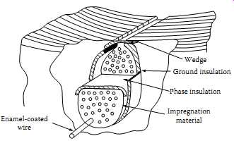
FIG 7 Cross section of the machine winding coils and insulation system.
Wedge Ground insulation Phase insulation Impregnation material Enamel-coated wire
===
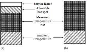
FIG 8 Total temperature measurements by (a) thermometer and (b) resistance
methods.
Service factor; Allowable hot spot; Measured temperature rise; Ambient temperature (a) (b)
===
TBL. 5 Insulation System Temperatures (°C) for Motors with 1.15 Service Factor
The temperature determined by the resistance method gives an indication of the average total temperature of the motor windings. The life of the insulation system is dependent on both the temperature rise and the total temperature of the motor windings. The total temperature for the various insulation classes is shown in TBL. 5. The motor temperature measurement by resistance method takes into consideration only two factors: the ambient temperature and the temperature rise measured by resistance at service-factor load. The sum of these two temperatures makes up the basis of total temperature of the insulation system. The resistance method eliminates the consideration of hot spot allowance, the 10°C allowance for service factor, and temperature rise measured by thermometer at nameplate load. Under the resistance method, the insulation system needed for the motor can simply be specified in terms of the operating ambient temperature and the service factor of the motor.
The use of the resistance method for the measurement of insulation temperature does not change the limitation imposed on the various classes of insulation systems. The resistance method has simplified the specification of the insulation temperature rating system for machine windings. As a result of this change in the temperature measurement method, the class B insulation system has been adopted as a standard for motor windings.