AMAZON multi-meters discounts AMAZON oscilloscope discounts
.If ever a single type of motor will be found to have characteristics suitable for nearly every application serviced by the many ac and dc motors traditionally used, it will likely be the dc brushless motor. In a way, this machine can be viewed as a dc mo tor in which electronic commutation replaces the commutator and brushes. The mere fact that the commutator-brush assemblage is dispensed with, implies low maintenance, low RFI and EMI, and low cost. But the electronic commutation pro vided by a dedicated IC does even more; it enables convenient “tailoring” of motor characteristics so that compromises that formerly attended the selection of a motor type need not apply. For example, such features as high starting torque and variable speed can now easily be realized together. And previous debates about the use of a dc or an ac motor tend to lose their relevance when a brushless dc motor is used with its accompanying dedicated IC.
One such dedicated IC is shown in the block diagram of FIG. 12. Tins IC is essentially concerned with electronic commutation; speed, torque, and direction control would be accomplished via the association of a separate PWM IC. Although the LM621 brushless motor commutator does not have on-board PW logic, there are other dedicated ICs that do. Advantages can be cited for both architectures. Having the commutation and control functions on separate ICs probably allows more flexibility in achieving specialized performance features. The pinout functions of the 1M621 are listed in Table 2.
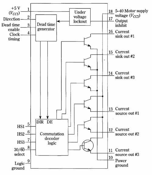
FIG. 12 Block diagram of the LM621 brushless dc motor commutator. This
dedicated IC enables mechanically-simple dc motors with no physical commutators
or brushes to be driven from a dc source.
Table 2. The pinout functions of the LM621 brushless dc motor commutator. The two common types of three-phase motors (30° and 60°), as well as four-phase motors (90°) can be accommodated.
Pin 1: V (+5 V). The logic and clock power supply pm.
Pin 2: DIRECTION. This input determines the direction of rotation of the motor; i.e., clockwise vs. counterclockwise. See truth table.
Pin 3: DEAI ENABLE. This input enables or disables the dead-time feature. Connecting +5 V to pin 3 enables dead-time, and grounding pin 3 disables it. Pin 3 should not be allowed to float.
Pin 4: CLOCK TIMING. An RC network connected between this pin and ground sets the period of the clock oscillator, which determines the amount of dead-time. See Fig. 2 and text.
Pin 5 thru 7: HS1, HS2, and HS3 (Hall-sensor inputs). These inputs receive the rotor- position sensor inputs from the motor. Three-phase motors provide all three signals; four- phase motors provide only two, one of which is connected to both HS2 and HS3.
Pin 8: 30/60 SELECT. This input is used to select the required decoding for three-phase motors; i.e., either “30-degree” (+5 V) or “60-degree” (ground). Connect pin 8 to +5 V when using a four-phase motor.
Pin 9: LOGIC GROUND. Ground for the logic power supply.
Pin 10: POWER GROUND. Ground for the output buffer supply.
Pins 11 thru 13: SOURCE OUTPUTS. The three current-sourcing outputs which drive the external power devices that drive the motor.
Pins 14 thru 16: SINK OUTPUTS. The three current-sinking outputs which drive the external power devices that drive the motor.
Pm 17: OUTPUT INHIBIT. This input disables the LM621 outputs. It’s typically driven by the magnitude signal from an external sign/magnitude PWM generator. Pin 17 = +5 V = outputs off.
Pin 18: V (+5 to +40 V). This is the supply for the collectors of the three current-sourcing outputs (pins 11 thru 13). When driving MOSFET power devices, pin 18 may be connected to a voltage source of up to +40 V to achieve sufficient output swing for the gate. When driving bipolar power devices, pin 18 should be connected to +5 V to minimize on-chip power dissipation. Undervoltage lockout automatically shuts down all outputs if the V supply is too low. All outputs will be off if V falls below the undervoltage lockout voltage.
As is commonplace with ICs intended for motor-drive purposes, important protective features “come along for the ride”. One of these is the adjustable dead-time feature, which eliminates current spikes that can be especially destructive when the motor is being braked or reversed. An undervoltage-lockout provision inhibits motor drive in the event of low motor supply voltage. The outputs can accommodate the gate-voltage swings for driving power MOSFETs, or can deliver 35 milliamps to each base of six bipolar power transistors.
Additionally, the LM62 us compatible with the drive requirements of both three- and four-phase dc brushless motors. Both, the 30° sensor displacement and the 60° sensor displacement types of three-phase motors can be handled. These accommodations are depicted in the commutator decoder truth table, Table 3.
Table 3. Commutator decoder truth table for the LM621 brushless-motor commutator. Table pertains to the two common types of three-phase motors, as well as to four-phase motors.
Note 1 The above outputs are generated when the direction input, pm 2, is logic high. For reverse rotation (pin 2 logic low), the above sink and source output states become exchanged.
Note 2: For four-phase motors sink and source outputs number two (pins 15 and 12) are not used; hence the “na” (not applicable) in the appropriate columns above.
The basic circuit arrangement for electronically commutating a three-phase dc brushless motor with the LM621 IC is shown in FIG. 13. Six N-channel power MOS FETs drive the motor’s delta-connected stator windings. The Hall-effect rotor position sensors connect directly to pins 5, 6, and 7 of the LM621. The effective magnitude of motor drive current is controlled via the duty cycle of pulses from an external pulse-width modulator circuit. This is tantamount to saying that motor speed is controlled by the pulse-width modulator. This is a nice technique of speed control because motor torque is not sacrificed at low speeds; the practical result is that a wide range of speeds can be obtained. Also, the low-speed cogging common to conventional dc motors is absent.
The PWM frequency is not critical; it will probably be in the audio or low super sonic region and can be determined empirically for best results. The size and winding characteristics of the motor will tend to govern this parameter. Originally, this motor control technique was applied to small motors, but successful applications have been made with fractional-horsepower motors. It now appears that dc brush- less motors of integral-horsepower capability can be efficiently controlled with electronic commutation and pulse-width modulation. Perhaps this technique can be extended for application to electric vehicles. If so, the ongoing controversy between dc and ac motors will end, because we will then have a motor combining the most desirable characteristics of both types.
The commutation waveform diagram for the motor-driven system of FIG. 13 is shown in FIG. 14. Notice that reversal of the direction of rotation is brought about by reversal of the sequence of drive currents to the stator windings. However a physical change of connections is not necessary; rather, reversal is accomplished via the logic sign applied to pin 2, which causes the source and sink output states to become ex changed.
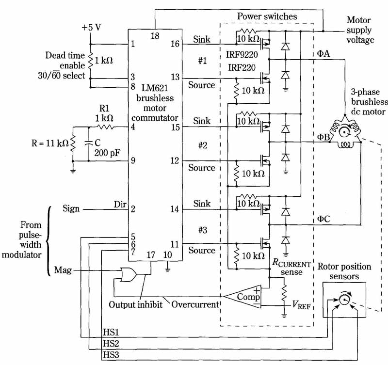
FIG. 13 Commutator scheme for a three-phase dc motor. This is representative
of a newly developing technology in which features of both dc and ac
motors are combined in a single machine. Operation is from a dc source
with no need of a mechanical brush-commutator system.
You might have noticed that the architecture of this motor resembles that of a three-phase synchronous motor, which also has a permanent-magnet rotor and either Y or delta-connected stator windings. In the synchronous motor, speed is determined by the drive frequency. In this application of the dc brushless motor, the frequency of the PWM pulses have no bearing on motor speed, providing the duty cycle of these pulses is not changed. In other words, it’s the effective drive current in the windings that governs speed. This mode of operation is due to the electronic commutation—in the ac synchronous motor, no such process interferes with the rotor’s “desire” to follow the rotating field. Incidentally, a good frequency for the PWM pulses is about 25 kHz because it’s above the audio range, but low enough to be faithfully reproduced by the switching transistors.
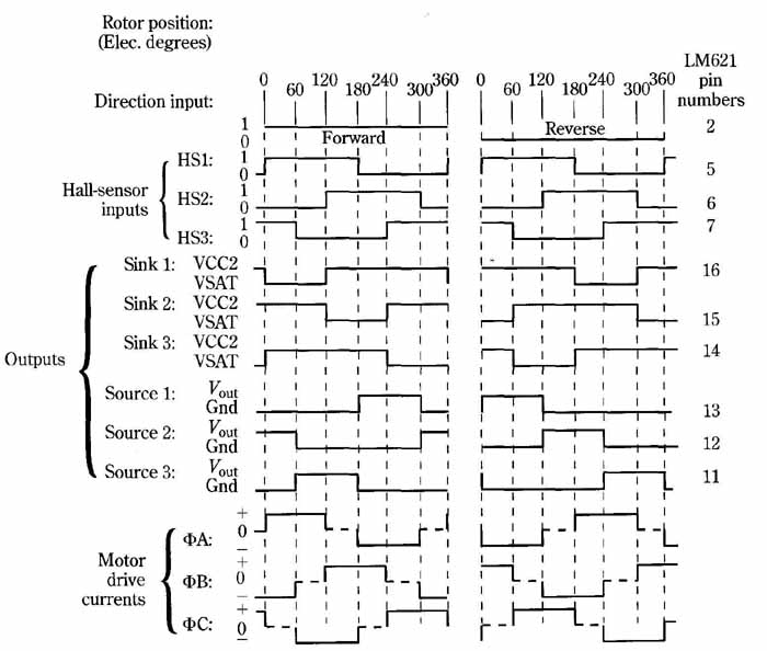
FIG. 14 Commutator waveforms for dc brushless motor with three-phase
stator. These wave forms pertain to machines in which the physical displacement
between the Hall-effect sensors is 30 degree.
Another manufacturer’s version of electronic commutation for brushless dc motors conveniently has the pulse-width modulator circuitry included in the chip. The block diagram of this dedicated IC, the Motorola MC33035 is shown in FIG. 15. Notice that the mere addition of an external potentiometer enables speed control of the motor. Also, an external resistance and capacitor allow for selection of the oscillator frequency. A practical frequency would be in the 20 kHz to 25 kHz region. The pin connections are explained in Table 4.
Table 4. Description of pin-functions of the MC33035 brushless dc motor controller. This IC is available in 24-pin dual-in-line plastic packages.
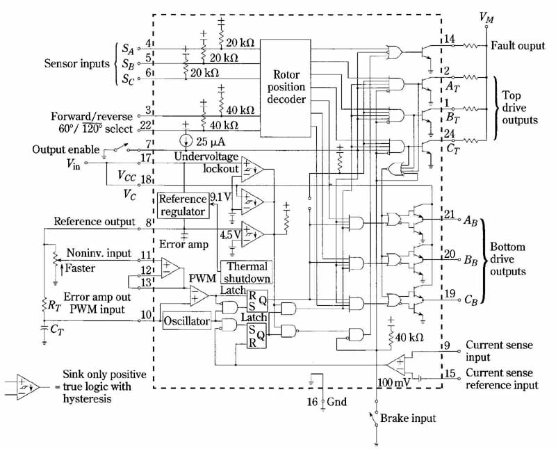
FIG. 15 Block diagram of the MC33035 dc motor control LC. The self-contained
PWM circuitry enables easy implementation in both, open-loop and in closed-loop
applications.
The circuit of a three-phase, six-step, full-wave motor control system is shown in FIG. 16 and the truth table for this system is shown in Table 5. Several practical differences from the previously discussed commutation arrangement are worthy of mention. This scheme shows a combination of bipolar power transistors and power MOSFETs as motor drivers (actually, the bipolar devices are Darlingtons). Fault-Output pin 14 enables an external LED to turn on in order to signify any of the fault conditions listed in Table 4. Activation of the LED is accompanied by deactivation of all motor-drive outputs. Note also, Brake Input pin 23, by which the motor can be rapidly decelerated. Such dynamic braking takes place when pin 23 is put in a high state; this causes the top-drive outputs to turn off and the bottom drives to turn on, shorting the motor-generated counter EMF. Brake input has unconditional priority over all other inputs. The bottom-drive power devices, power MOSFETs in this case, have to be selected with ample current capability.
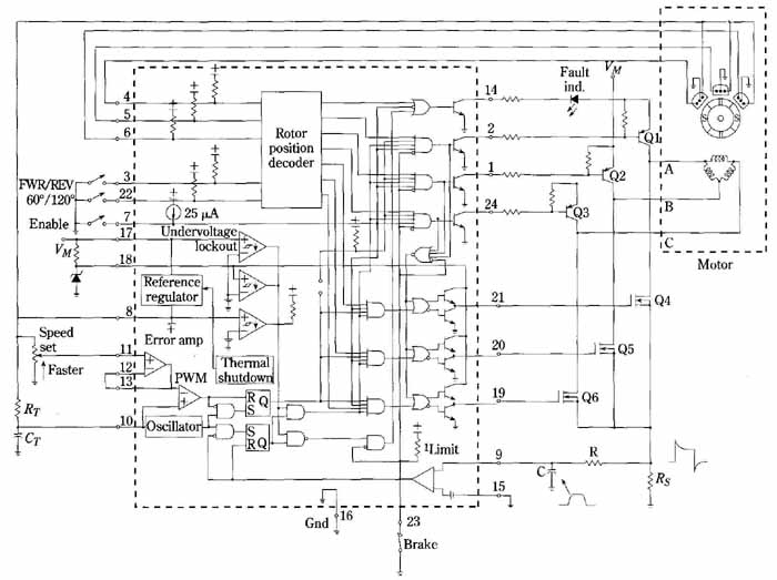
FIG. 16 Three-phase, six-step, full-wave motor control system. The
MC33035 IC provides electronic commutation for the three-phase brushless
dc motor. Open-loop control of speed is accomplished by adjusting the
duty cycle of the three bottom power-MOSFETS.
All told, these differences from the previously discussed commutation system don’t constitute drastic variances. Both company’s control schemes are of the open-loop type. Closed-loop regulation of speed can be implemented in both with the same design philosophy as used in PWM voltage-regulated power supplies. That is, a sampled-voltage representing motor speed is introduced at the input of the error amplifier, the output of which causes duty-cycle variation from PWM circuitry; the power-boosted pulses are then applied to the motor and counteract any tendency for it to change its speed. This is particularly straightforward with the MC33035 IC, where the output of a motor-mounted dc tachometer can be applied to pin 12 of the error amplifier. An alternate method is to use the pulsed output of one of the Hall-effect sensors to provide the speed information to the error amplifier. The circuit implementation of this method is shown in FIG. 17. A similar implementation using a dedicated IC for greater precision is shown in FIG. 18.
Table 5. Three-phase, six-step commutator truth table.
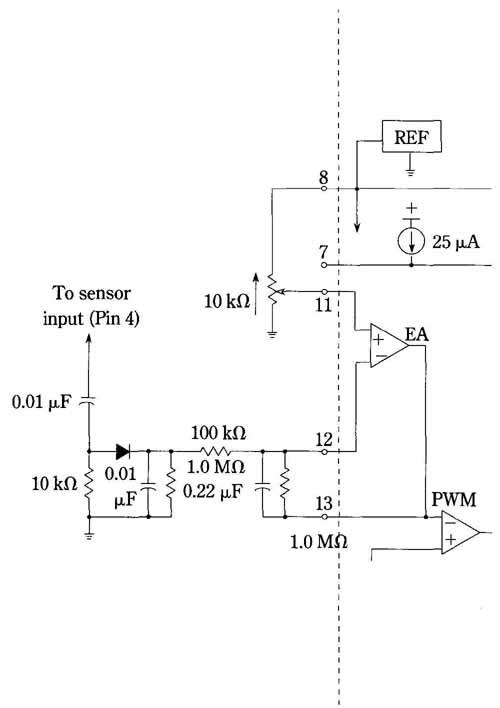
FIG. 17 Closed-loop speed regulation via the use of a motor sensor.
The pulses obtained from the HALL-effect sensor are proportional to motor
speed. Therefore, a physical tachometer is not needed.
Further insight in to the operation of the MC33035 open-loop system can be gleaned from a study of the truth table of FIG. 19, and the waveform diagram of FIG. 19, in which two operational modes are depicted, one for full speed (100-percent duty cycle), and the other for reduced speed at 50-percent duty cycle. Even though only the bottom-drive outputs can be duty-cycle modulated, the three motor drive currents are symmetrical. Thus , for the reduced-speed operation, you see the PWM ripple on the A, B, and C phases of motor drive current.
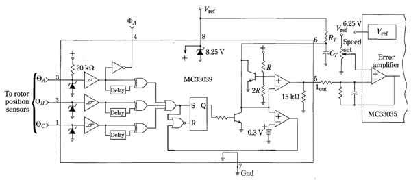
FIG. 18 Closed-loop speed regulation via the use of the motor sensor
and a dedicated IC. The principle is similar to that shown in FIG. 17,
but the special MC33039 allows for more precise regulation.
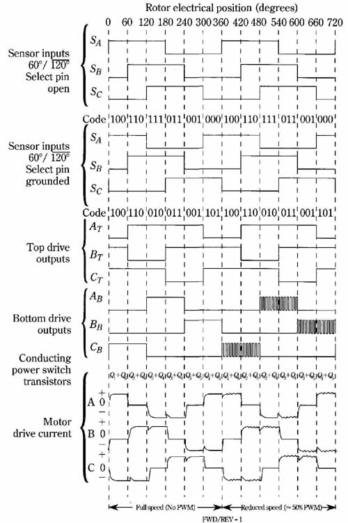
FIG. 19 Three-phase, six-step, full-wave commutation waveforms. Full-wave
infers bidirectional current in each stator winding.
