AMAZON multi-meters discounts AMAZON oscilloscope discounts
.At an earlier developmental stage, the Darlington power transistor was not looked upon favorably as a power device for actuating and controlling motors. Inasmuch as the Darlington transistor does not saturate, it was argued that relatively high power dissipation would lead to low operating efficiency. And, the early Darlington transistors displayed obviously poor characteristics for motor work—they had inadequate power-handling capability and were easily damaged by current surges and voltage transients. Several things have happened to change this picture. First and foremost, modern Darlington transistors have become respectable power devices. As such, they are electrically rugged to the extent that they merit serious consideration as substitutes for SCRs in many applications. This is readily seen from the availability of Darlington transistors capable of withstanding 400 volts and with 20-ampere cur rent capability. Collector dissipation, because of non-saturation, is of negligible con sequence at high operating voltages, say above 100 volts.
Interestingly, it’s one of the Darlington’s alleged “drawbacks”—inability to saturate—that now compels its use in motor-drive systems. Its inability to saturate is largely responsible for its efficient chopping operation in the 20-kHz region. This enables the highly efficient and flexible pulse-width modulation technique to be implemented at frequencies where SCRs are not likely to be at their best. This is especially so considering the freedom gained from commutation problems when substituting the Darlington transistor for the SCR.
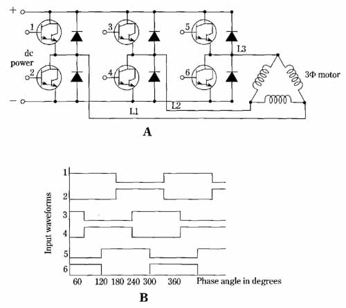
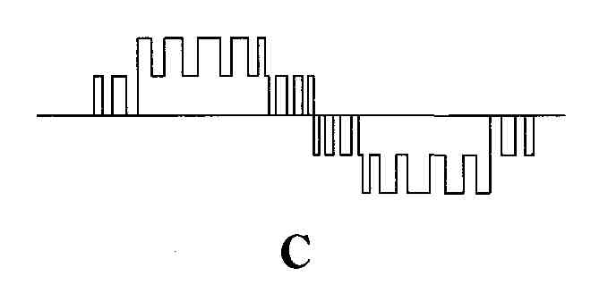
FIG. 22A shows an array of Darlington transistors arranged to provide ac power to a three-phase motor. The input waveforms necessary for such direct production of motor drive power are shown in FIG. 22B. The best use of the Darlintgton inverter results when the bases are driven with high-repetition rate width-modulated pulses, as shown in FIG. 22C. The use of this waveform enables automatic variation of both, the frequency of the reconstituted sine wave and its amplitude (an induction motor’s voltage requirement is inversely proportional to frequency).


FIG. 22 The use of a Darlington inverter to supply ac motor power.
(A) Array of Darlington switching transistors for inverting dc to three-phase
ac. (B) Base input waveforms for direct development of desired drive
frequency. (C) Fabricated sine wave when pulse width modulation is used.
The pulses have a repetition rate much greater than the simulated sine
wave.
Considerable simplicity in inverter design is afforded by the modern monolithic Darlington device. Not only are both transistors integrally packaged, but so are the emitter-base resistors and the free-wheeling diode.