AMAZON multi-meters discounts AMAZON oscilloscope discounts
.The traditional way of shortening the coasting time of a commutator motor following turn-off is to consume current from the still-rotating armature. The machine
A. Operation from a single-phase power line.
B. Operation from a two-phase power source.
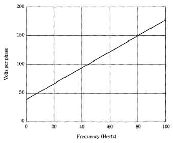
FIG. 19 Required voltage when constant-torque output is desired from
a Slo-Syn motor. Superior Electric Co.
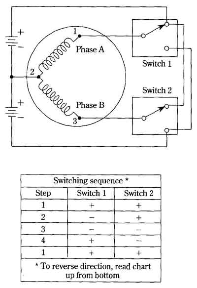
FIG. 20 Switching logic for sequential stepping of the Slo-Syn motor.
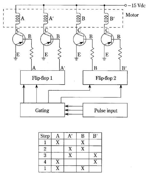
FIG. 21 Sequential stepping-logic for bifilar Slo-Syn motor and single-ended
power supply.
then becomes a generator, and the electrical energy it delivers is derived from the kinetic energy stored in its rotating members. Rotation is therefore quickly decelerated, and the motor is brought to a standstill in much shorter time than it would be from windage and bearing friction (see Fig. 24). Non-commutator motors, how ever, are not suitable for this method of dynamic braking.
Two-phase and three-phase induction motors can be dynamically braked by “plugging,” that is, by attempting reverse rotation. This is accomplished in these polyphase motors by transposing power-line connections to one phase of the motors stator winding. Because the permanent-capacitor, split-phase motor is, in essence, a two-phase machine, it too can be dynamically braked by the ordinary reversing technique. Of course, all motors braked by attempted reversal must be disconnected from the power line before actual reverse rotation occurs. The resistance-start induction motor, or what is loosely referred to as a “split-phase” motor is not readily braked by transposition of its windings, nor is the capacitor-start induction motor. The basic idea is that those motors, which ordinarily should not be reversed until the shaft is at rest, should not be subjected to the “plugging” techniques.
All ac motors with squirrel-cage rotors can be dynamically braked by injecting dc into one, or more, of their windings following disconnect from the ac power line. In essence, such machines then become separately excited dc generators with shorted armatures. Such braking can be very effective, and there is no tendency for reverse rotation. Immediately after standstill is achieved, the dc should be disconnected to prevent heating of the stator winding(s).
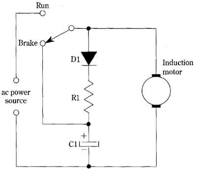
FIG. 22 Dynamic-braking technique for ac motors with squirrel-cage rotors.
A more sophisticated method for accomplishing such braking is to dump the electric energy stored in a capacitor into one or more stator windings of squirrel- cage motors. The circuit shown in FIG. 22 is applicable to shaded-pole motors and all other ac motors with squirrel-cage rotors, providing they are not too large—V hp is perhaps a practical limit because of the inordinate capacitor size required for larger machines. Depending on the motor size and the deceleration desired, capacitors up to hundreds of microfarads are feasible for many braking requirements. Diode D1 can be a silicon rectifier with a current rating of several amperes. Resistor R1 can be a two-watt composition resistor of about 50 k or so.
Synchronous motors can usually be braked by the application of dc to the stator, but the decelerating mechanism is somewhat different from that of induction motors. Empirical investigation is often required for optimum results. A possible ad vantage attending dynamic braking of synchronous motors is their ability to lock in position once brought to a standstill. This “holding” behavior is most pronounced in the reluctance synchronous motor.
