AMAZON multi-meters discounts AMAZON oscilloscope discounts
.The polyphase induction motor is probably the most important type of motor used in industry. The motor is inherently self-starting, and it’s very efficient in its conversion of electrical energy to mechanical energy. Polyphase excitation of appropriately designed stator windings produces the rotating field that is only simulated by the various devices employed for the starting of single-phase motors. Because this rotating field is symmetrical, torque development is smooth and relatively noiseless.
Although the majority of industrial induction motors are three-phase machines, the primary requisites for achieving polyphase operation are simpler to discuss for a two-phase motor. A basic two-phase induction motor is illustrated in FIG. 19. Although four stator windings are symbolically shown, the motor has only two poles per phase. In analogous fashion, a two-pole, three-phase motor would have six separate stator windings spaced at 60-degree intervals. The two-phase induction motor is of ten encountered in servo systems where the two-phase power can be conveniently generated by solid-state circuitry. Actually, the structure depicted in FIG. 19 is virtually the same as that described for the permanent-capacitor induction motor. The chief difference between the two motor types is that the two-phase power source had to be artificially produced for the permanent-capacitor motor, whereas such a source is assumed to be available for the two-phase induction motor.
There is nothing unique about the squirrel cage of polyphase machines. Considerable variation in speed regulation and starting torque can be achieved by certain design manipulations involving the resistance of the bars, their number, and the way they are embedded in the armature slots.
Although it’s customary to show salient poles in diagrams such as FIG. 19, actual induction motors generally have distributed stator windings. It would be rather difficult to determine the number of poles in a stator from visual inspection; you would also have to analyze the way in which the windings were connected.
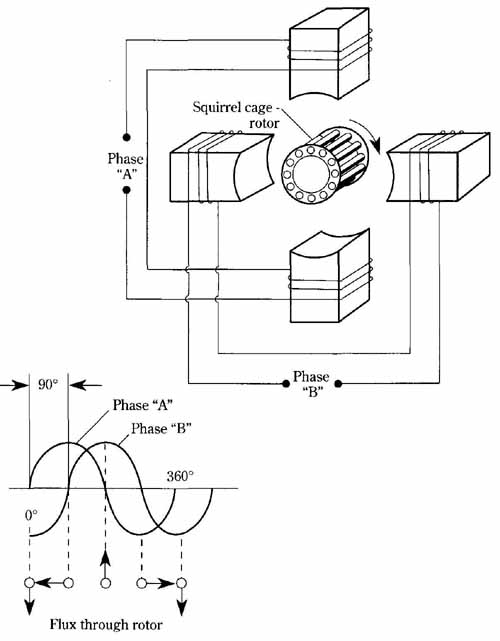
FIG. 19 A two-phase, two-pole squirrel-cage motor—the simplest polyphase
machine. Flux through rotor
In FIG. 19, the flux arrows represent only instantaneous polarities—the field being in spatial rotation. Interchanging the motor connection of phases “A” and “B,” with respect to the two-phase supply, reverses the direction of rotation. In a three- phase induction motor, the interchange of any two of the three power-line connections will reverse rotation.
A wound-rotor, three-phase induction motor is shown in FIG. 20. This drawing is more of a schematic than the pictorial representation shown for the two-phase induction motor. The number of poles in the stator cannot be determined from this drawing; the motor could have any even number of poles. Although the delta connection is shown for the stator, the windings can be designed for connection in the Y configuration, as well. So far, I have not mentioned any difference between this motor and the two-phase machine of FIG. 19, except for the different number of phases. If the motor of FIG. 20 were depicted with a squirrel-cage rotor, it would be the three-phase version of FIG. 19.
The real difference between the motor in FIG. 20 and squirrel-cage machine is its wound rotor. Instead of being shorted upon itself, the leads from this rotor are brought out through slip rings. It might appear that this is merely another way of constructing an induction motor. However, the resistance of the wound rotor, and the resistance that might be added with rheostats, develops important operational differences for this motor when compared with the squirrel-cage type.
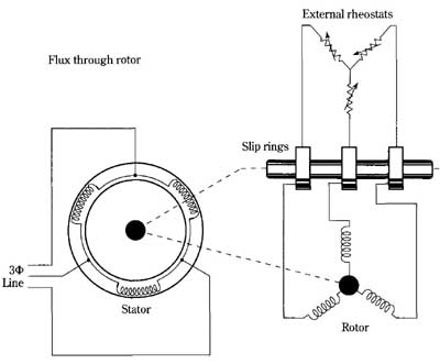
FIG. 20 The wound-rotor, three-phase induction motor. Flux through
rotor; External rheostats; Rotor
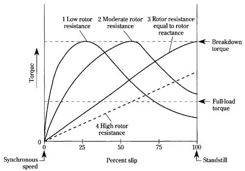
FIG. 21 Torque control by changing rotor-circuit resistance. 1 Low rotor;
2 Moderate rotor resistance; 3 Rotor resistance equal to rotor resistance;
Breakdown torque; Full-load torque
Inserting resistance in the rotor has two effects. The slip can be considerably in creased, thereby providing a method of speed control. Additionally, the starting torque can be made significantly higher. Actually, the maximum torque can be made to occur at 100 percent slip, that is, at standstill, just as the motor is started. This optimum starting situation is realized when the resistance and reactance of each phase are equal. FIG. 21 shows the control of motor torque by adjustment of rotor resistance. The wound-rotor motor has better starting characteristics and more flexible speed control than its squirrel-cage counterpart. However, it exacts payment for these advantages by having poorer speed regulation and poorer operating efficiency. In FIG. 21, the resistance of the rotor circuit is made higher as you progress from curve 1, to curve 2, and to curve 3. If the rotor resistance is increased beyond its value in curve 3, it can be seen that the maximum torque capability of the motor is no longer attainable at standstill, or at any other speed. This is the situation shown by curve 4.
---- --