AMAZON multi-meters discounts AMAZON oscilloscope discounts
The series motor
In the series motor, field excitation is derived from windings comprising relatively few turns of heavy wire connected in series with the armature. Because of this arrangement, field and armature current are the same. Obviously, the armature and field must experience different interactions in the series motor than in the shunt motor. This is immediately evident in the speed and torque curves of FIG. 14. Because the armature and field currents are identical, the basic motor torque equation, T = k PHI I_a can be expressed in the form, T = kI_a^2 for the series motor. Thus, torque is an exponential function of armature current as shown in the plot for torque versus armature current.
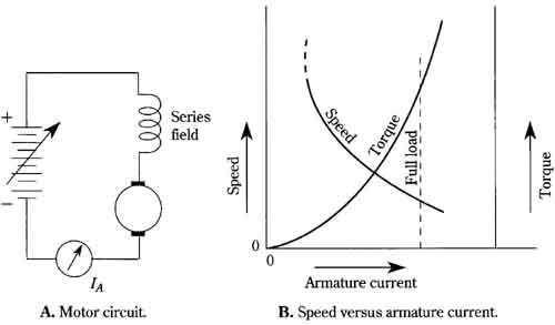
FIG. 14 Basic characteristics of the series motor. A. Motor circuit. B. Speed
versus armature current. Series field; Armature current, Speed and torque vs.
armature current
You might already be aware that the series motor is usually selected for applications where high starting torque is needed, such as in traction vehicles. Paradoxically, the torque in the vicinity of standstill and at low speeds appears to be inferior to that of the shunt motor. However, at standstill, a motor is in an overloaded condition—there is no counter EMF to impede the inrush of current. It is here that the series motor is advantageous. The initially high armature (and field) current generates a very high torque. Thus, in FIG. 14B it is actually the torque depicted to the right of the full-load line that accounts for the excellent starting ability of the series motor. (In practice, magnetic saturation sets in and the starting torque is not as high as it would otherwise be.)
The speed characteristics of the series motor also favor those applications where high torque automatically becomes the trade-off for speed. Such a situation is found in traction vehicles and also in many power tools. A shortcoming of the series motor is its speed-runaway feature at light loads, and particularly at no load. Small motors can be protected by their own bearing friction and windage, but most series motors tend toward self-destruction if the load is decoupled from the shaft. Unlike the runaway in shunt motors, the accelerated racing of the series motor is accompanied by decreasing armature current. Fuses or circuit breakers in the line, therefore, cannot provide protection against such a catastrophe.
Reversing the polarity of the dc power source does not reverse the rotation of the series motor because both armature and field flux are thereby changed and the magnetic torque remains in the same direction. Reversal must be made by transposing the connections of either the armature or the field. By the same reasoning, many series motors will operate fairly well on ac. Optimized ac performance is attained in specially designed series motors, known as universal motors.
The compound motor
The compound motor, as its name clearly implies, is a combination type. It incorporates the techniques of both the shunt motor and the series dc motor. Inasmuch as it is both a shunt and a series motor, it might reasonably be expected to display some of the characteristics of each type. This, in essence, is true and accounts for the popularity of compound motors. By appropriate “blending,” the no-field run away behavior of the shunt motor and the no-load runaway characteristic of the series motor can be eliminated. The connections used in compounding are shown in FIG. 15. Actually, the difference in performance between the “short” and “long” compounding is generally not of appreciable consequence. Other factors, such as convenience of terminations, reversing considerations, and internal connections to interpole and compensating windings, usually dictate the choice of these near-equivalent connections.
On the other hand, the way in which the shunt and series windings are polarized with respect to one another has a great effect on the operating characteristics. Clearly, the two fields can either aid or oppose in the production of magnetic flux. If the shunt and series fields are connected so that their fluxes aid, the motor is said to be cumulatively compounded. If their fluxes oppose, the motor is differentially compounded. These connection techniques have nothing to do with short- and long-shunt connections. In a given machine, if either the series- or the shunt-field connection is transposed, the nature of the compounding changes—if cumulative compounding had previously been used, the transposition converts the machine to the differential type, and vice-versa. A given machine may, or may not, be intended for both types of compounding. Usually, a motor behaves optimally for only one kind of compounding.
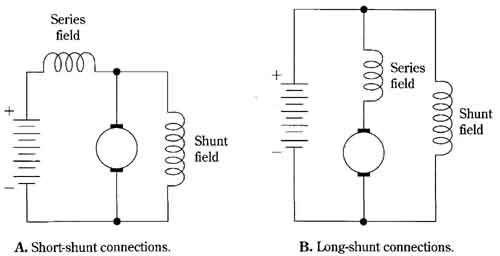
FIG. 15 Compound motor connections. A. Short-shunt connections. B. Long-shunt
connections. Series field, Shunt field
FIG. 16 shows the torque and speed behavior of compound motors as a function of armature current. These characteristic curves are often considered in terms of their deviation from similar plots for the shunt motor. Because the compound mo tor merges the features of both shunt and series motors, the curves of FIG. 16 depict the behavior of all four motor types.
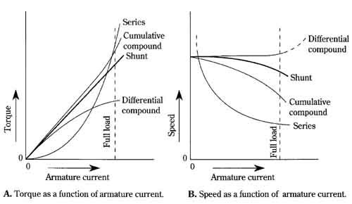
FIG. 16 Torque and speed characteristics of the four basic dc motors. A. Torque
as a function of armature current. B. Speed as a function of armature current.
Differential compound; Shunt; Cumulative
The user’s comparison of motor ratings
In the classification of motor characteristics, one of the first parameters that comes to the mind of the user is the horsepower output rating. Although the engineer might have derived his or her basic design from the behavior of a motor with respect to armature current, the buyer will probably be motivated more by the cost relative to the mechanical output. This has already been mentioned in connection with the available torque from a machine. The nameplate on a motor usually specifies its shaft output in terms of horsepower, if for no other reason than that most work demand is specified in this way.
The other shaft quantity, torque, must be accompanied by a speed designation to be meaningful in practical motor situations, So, if both torque and speed are specified, one can also resort to a horsepower rating, which-is proportional to the product of torque and speed. Of course, that all-important quantity, starting torque, involves zero speed—here torque is a useful concept even when horsepower output is zero. Therefore, many applications are best met by considering motor behavior as a function of torque.
The torque and the speed characteristics of the four basic dc motors are shown as functions of shaft horsepower in FIG. 17. These curves are particularly useful for comparing the performance of motors because the plotting assumes that all motors have the same full-load horsepower rating.
A useful feature of the compounding technique is that motor characteristics can be tailored to fit requirements. For example, the speed regulation of a shunt motor can be improved by introducing a small amount of differential compounding—often a very nearly constant speed can be had in this way. Some compounded motors are essentially series-type machines with a small amount of cumulative compounding from a shunt field winding. Other combinations and proportions can be used to fit the purpose at hand.
A word of caution is in order with regard to the differentially compounded mo tor. This combination is susceptible to racing at high loads because the opposing series field tends to grossly weaken, or even overcome, the field flux produced by the shunt winding. Protective circuitry is indicated here, with armature current as the “sensed” quantity.
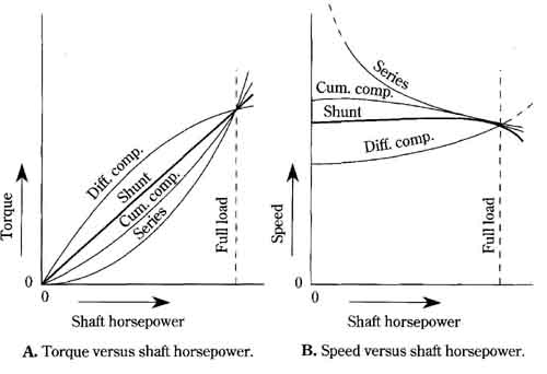
FIG. 17 A user-oriented comparison of the four basic dc motors. A. Torque
versus shaft horsepower. B. Speed versus shaft horsepower.
A motor is also a generator
As already pointed out, dc motors and generators are, in principle, very nearly the same. What differences there are have to do with optimization of certain operating features, primarily commutation. Many actual machines are capable of rendering satisfactory service when employed in either function. And, no matter what the “normal” function of a dc machine is, the alternate function is always taking place simultaneously. Thus, you have counter EMF in motors, and you have countertorque in generators. This fact is brought out even more emphatically when dynamic braking is used—that is, when the coasting interval of a motor is shortened by dumping its generated power into a resistor or back into the power line. It follows that a knowledge of generator characteristics is bound to sharpen one’s insight into dc machines even if one’s primary interest is motors.
The basic dc generators are depicted in FIG. 18. The simplest machine, the permanent magnet type shown in FIG. 18A, is often the most precise. This accounts for its popular use as a tachometer. In such service, extreme linearity, high-grade construction, and other instrument-like qualities are often incorporated in its design.
The series generator is shown in FIG. 18B. This generator cannot build up without a load. Its characteristics are somewhat wild, but nonetheless they are very useful for certain applications. The series field comprises a relatively few turns of heavy conductor, capable of carrying the full armature current. (Resemblance to the series motor is intentional.)
The shunt generator can be operated in two distinct ways—as a self-excited ma chine, as shown in FIG. 18C, or in the separately excited mode, as illustrated in FIG. 18D. The self-excited shunt generator depends on residual magnetism in its pole structure to initiate the buildup process. And, in contrast to the series generator, buildup becomes more difficult with load application. It is often desirable to disconnect the load while the machine is being placed into operation. The separately ex cited generator involves no buildup problem. In this respect, as well as in others, its performance parallels that of the permanent-magnet generator. (“Build-up” designates the regenerative sequence of events that enables a generator with no external field excitation to develop full operating capability after being pressed into service. Because of residual magnetism in the field poles, a little bit of armature voltage is developed. This reinforces field excitation, which in turn results in more armature voltage, etc. After a few seconds, or a few minutes in large generators, the process stabilizes because of magnetic saturation.)
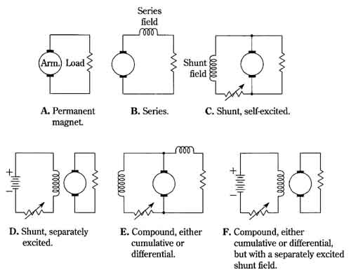
FIG. 18 The basic dc generators. A. Permanent magnet. B. Series. C. Shunt,
self. D. Shunt, separately excited. E. Compound, either cumulative or differential.
F. Compound, either cumulative or differential, but with a separately excited
shunt field.
Characteristics of the basic dc generator
The characteristics of the basic generators are illustrated in FIG. 19. It is assumed that all machines are driven at a constant speed. As previously mentioned, the plot of terminal voltage versus load current for the series generator, as shown in FIG. 19A, is “wild.” However, the fact that the terminal voltage increases with load cur rent throughout most of the operating range can be useful. Such a characteristic can provide automatic compensation for the natural voltage drop occurring in long trans mission lines. However, a better implementation of this technique results when the series generator characteristic is merged with the shunt generator characteristic. The right-hand portion of the characteristic curve of FIG. 19A approximates that of a constant-current source. In this operating mode, the series generator has proved useful as a power source for welding and for certain arc-lamp systems.
The characteristics of compound generators are shown with reference to those of the shunt generator in FIG. 19B. The so-called flat compound machine derives its name from the fact that the no-load and rated-load terminal voltages are the same. At other loads, there is a departure from the ideally flat characteristic. Flat-, under-, and over-compounding differ in the amount of series characteristic introduced. The differential-compound characteristic resembles that of the high-load-current region in the series generator, and the applications are similar.
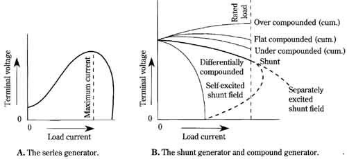
FIG. 19 Characteristics of the basic dc generators. A. The series generator.
B. The shunt generator and compound generator.
The slower a generator is driven, the more field excitation it must have in order to maintain its full-load capability. And, because slower speeds involve operating more deeply into the magnetic-saturation region of the pole structures, the voltage regulation of the shunt and the cumulative compound generators improves. (That of the differential compound generator, already bad, becomes worse; however, its constant-current characteristic improves.) Driving a genera tor below its rated speed might not always prove to be a desirable trade-off because the efficiency decreases.
Some unique aspects of modern permanent-magnet motors
At first glance, the characteristics of the shunt-wound motor and the permanent- magnet motor might appear to be similar. It would seem to make little difference to the armature current whether it interacted with a field produced by an electromagnet or a permanent magnet. Indeed, many motor control circuits allow the option of using either of these dc motors.
However, there are important differences. Some of these differences are not indicated in older texts and handbooks. For example, it was once commonly held that the permanent-magnet motor was suitable for applications where greater size and weight were not objectionable. Because of modem magnetic materials, this situation is now reversed. FIG. 20 shows the relative frame sizes of a 1/4-hp permanent magnet motor with its ferrite-ceramic poles and a shunt-wound motor of the same horsepower rating. Various alloys of Alnico magnet material are also used in motors.
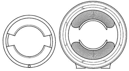
FIG. 20 Frame sizes for a ¼ hp ferrite ceramic permanent-magnet motor and
a 0.25hp Hunt-wound motor.
In general, the permanent-magnet motor tends to be smaller in size, lighter in weight, more efficient, and more reliable than its shunt-wound counterpart. This statement could not have been made just a few years ago when the first ceramic-field motors were used in toys and other noncritical applications. The earlier steel-magnet motors suffered in reliability because of their susceptibility to demagnetization.
FIG. 21A compares the speed/torque relationships for the two types of motors. The fact that the rated 1/4-hp output is developed at somewhat different shaft speeds is not of appreciable consequence in this comparison. Those accustomed to the general nature of the speed/torque relationship in shunt-wound motors are often startled by the greatly extended characteristics of the permanent-magnet motor. For example, in FIG. 21A the linear slope of speed regulation continues right down to standstill as more torque is extracted by the mechanical load. This implies that the permanent-magnet motor has a starting-torque capability several times that of its shunt-wound counterpart. Additionally, the speed as a function of load is easier to predict. This is even more clearly shown in FIG. 21B where the armature is subjected to various voltages.
The surprising performance differences in permanent-magnet motors stem from the much smaller effect of armature reaction on field strength. The high coercive force of modem magnetic materials is primarily responsible for this.
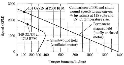
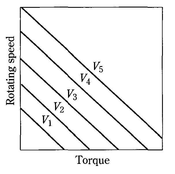
FIG. 21 Unique characteristics of the modern permanent-magnet motor.
A. Comparison of the permanent-magnet motor and a shunt-wound motor. B. Speed/torque relationships of a permanent-magnet motor for various armature voltages.