AMAZON multi-meters discounts AMAZON oscilloscope discounts
The basic precepts of motor action presented in section 1 now leads to consideration of more specific matters. In the interest of ultimately dealing with electronic controls, it serves our objective to discuss the operating characteristics of motors and generators. In so doing, I will touch on the “old” (and often prevailing) methods of controlling rotating machines. It is hoped that the discussions of operational behavior and control characteristics will set the stage for the final sections in which the actual electronic control techniques are discussed. The rationale for such a format is that, unlike the staid, rarely changing methods used up to now to control electrical machines, the methods of electronic control technology are dynamic, subject to constant improvement, and ever increasing sophistication, and are obligingly responsive to one’s creative prowess.
This section deals with the important features of the classical direct current machines. What is implied by the reference to “classic” motors and generators? It has happened that over a span of many years, certain types of machines have become associated with unique operating behavior. Although it might be that no systematic classification was ever formally devised, it certainly is a fact of life that one has evolved. From the point of view of applying electronic controls, this is very much in our favor. The first thing to know when implementing electronic control devices are the “natural,” or noncontrolled, characteristics of the motor or generator. The second thing is how was control accomplished prior to the advent of solid-state devices.
An interesting fact relevant to “classic” dc machines is that they are actually ac devices. The contradictory nature of such a statement stems from the fact that the rotating armatures of these machines carry alternating current, not direct current! That is why the commutator can be found on both motors and generators. In what is ordinarily termed a dc motor, the commutator changes the applied dc to ac for actual application to the armature conductors, while in the dc generator, the very same commutator is used to rectify the generated ac so that an essentially direct current is delivered to the load. An immediate consequence of such a revelation is that the armatures of these machines must be fabricated of laminated sheets, as are other ac devices such as transformers. Such construction greatly diminishes the induction of dissipative eddy currents within the iron of the rotating armature. If only dc were involved, such a scheme would be unnecessary.
Enhanced motor action from the use of iron or other ferromagnetic materials
Another approach, generally more practical, to motor action is similar to that de scribed for the electrodynamic wattmeter and the commutator-type watt-hour me ter. However, the current-carrying conductors are exposed to magnetic flux from iron-core electromagnets or from permanent magnets. Because of the much more powerful magnetic fields, significantly higher torques are developed. And, as will be shown, the presence of iron brings about important operational differences in practical motors as well. In FIG. 1A, a current-carrying conductor is situated in the magnetic field produced by either a permanent magnet or an iron-core electromagnet. This conductor experiences an upward force. More specifically, the force is also directed at right angles to the magnetic flux supplied by the magnet. A downward, or oppositely directed, force would be experienced if the current through the conductor were reversed, or if the north and south poles of the magnet were reversed. (If both the current and the poles were changed, the upward thrust of the conductor would remain unchanged.)
The magnitude of the force developed on such a current-carrying conductor is proportional to: the product of the magnetic field strength from the magnet; the amount of current carried by the conductor; and the length of the conductor ex posed in this manner to the magnetic field. In most practical devices, multiple conductors are involved rather than just a single conductor. The windings on motor armatures, for example, are intended to accomplish such a situation. The mechanical force produced must then also be proportional to the number of current-carrying conductors, as well as to the three factors just mentioned.
Notice in FIG. 1 that the composite field in the immediate vicinity of the cur rent-carrying conductor is distorted. Indeed, without such field distortion, there can be no force developed on the conductor. For example, if no current flows through the conductor, no circular magnetic field will surround the conductor, and there will be no distortion of the main field. In turn, no force will be experienced by the conductor. These apparently simple facts have important ramification in electric motors. On the one hand, the more field distortion, the better. But excessive deflection of the main field also brings about certain operating difficulties.
The D’Arsonval meter movement shown in FIG. 2 is an example of motor action with the use of iron. In this device, the stationary iron core deflects the magnetic field as shown so that the scale divisions can be uniformly spaced. Although this particular scheme is not used in motors and generators, the manipulation of field direction in rotating machines is very important with regard to obtaining proper commutation.
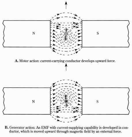
FIG. 1 Current-carrying conductors in fields produced by ferromagnetic material.
A. Motor action: current-carrying conductor develops upward force. B. Generator action: An EMF with current-supplying capability is developed in conductor, which is moved upward through magnetic field by an external force.
Motor and generator action
Returning to FIG. 1, the cross signifies electron current directed into the page; the dot signifies electron current directed out of the page. In FIG. 1B, no external source of voltage is employed to drive current through the conductor, and the up ward motion of the conductor, instead of being developed, is supplied. This is basic generator action. (Of course, the conductor must be part of a complete circuit for actual current to flow.) Internally, the field distortion has changed. At this point, the change has been such that it opposes the direction of physical motion supplied to the conductor. (This is a manifestation of Lenz’s law.)
The significance of FIG. 1 is not so much that the motor and generator actions are reciprocal functions—you supply electrical energy and derive mechanical energy, or conversely, you supply mechanical energy and induce an EMF with current-delivering capability. The significance, at least from the standpoint of control techniques, is that these two functions occur together in any one machine, whether it is called a motor or a generator. The voltage induced in the moving conductors of a machine operating as a motor is called the counter EMF. For a machine to run as a motor, the voltage applied to its terminals must be greater than the induced voltage, or counter EMF, from its own generator action.
In a machine that is operating as a generator, the internal motor action opposes the torque supplied to the machine. In order for the machine to run as a generator, the applied torque must overcome the internally produced torque. Referring now to FIG. 3, try a simple experiment that will clarify the simultaneous motor/generator action described earlier. First, let the battery and the voltmeter be connected to the dc motor (POSITION 1). Then disconnect the battery, allowing the motor to coast to standstill (POSITION 2). When the disconnect is first made, the voltmeter reading becomes only slightly less than when the battery is supplying motor current. The machine now is functioning as a generator, just as it did prior to the disconnect when its primary function was that of a motor.
In the preceding experiment, if a load is placed across the machine’s terminals while it is still coasting (POSITION 3), it very quickly slows down and comes to a halt. This demonstrates that it is internally developing motor action while functioning primarily as a generator. This motor action obviously opposes the direction of rotation while the machine is behaving as a generator to deliver electrical energy to the load. As can be anticipated, these characteristics will be found intimately related to control techniques.
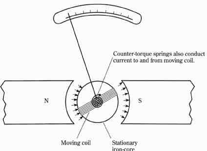
FIG. 2 The D’Arsonval movement is an example of use of ferromagnetic materials.
Moving coil; Stationary iron-core
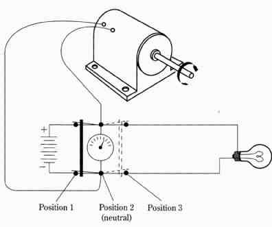
FIG. 3 Demonstration of simultaneous motor and generator action in same dc
machines.
A disadvantage of the commutator
At an appropriate instant during the rotation of a dc motor, its commutator must re verse the current through those armature conductors, which having left the influence of a field pole, are approaching that of an alternate pole. In this way, unidirectional torque is produced, leading to continuous rotation. But, the physical fact that a brush can contact more than one commutator segment is not a trivial matter because an armature loop can thus be shorted out. Obviously, the short endures for only a tiny fraction of the time required for one revolution of the commutator. However, if the shorted armature loop has a difference of potential across its ends, severe sparking can occur at the interface of the brush and commutator segments. At worst, such sparking produces burning and pitting of the commutator; at best, it results in erratic brush contact and the generation of needless RFI (radio frequency interference). Because there is no way to avoid the shorting of adjacent commutator segments, it is necessary to ensure that no voltage is induced in the commutator loop undergoing the momentary short.
The shorted condition is progressively experienced by all of the loops as their commutator segments rotate under the brushes. The action is similar for both brushes. Whether the machine is operating as a motor or as a generator, voltage will be induced in the rotating armature loops when they “cut” magnetic lines of force in the main field. If the short is occurring at the instant the active conductors in the armature loop are moving parallel to the field, no generator action takes place, apparently making it “timely” to accommodate the momentary short at the commutator segments. The vertical axis occupied by the shorted armature loop is known as the geometric neutral plane. It would appear that, in principle, such a technique should result in clean, sparkless commutation. Unfortunately, in actual machines, the situation is somewhat more involved.
The ensuing discussion show that the geometric neutral plane is more important than our description might imply. For more than one reason, the geometric neutral plane is not necessarily the place where the commutator can be allowed to undergo its shorting action. In any event, keep in mind that it is the current-reversing action of the commutator/brush system that is desirable—the shorting action is not. This situation, incidentally, has spurred the development of commutatorless machines in which the current-reversing process is accomplished with solid-state devices.
Armature reaction
After you grasp the fact that simultaneous motor and generator actions occur in dc machines, it becomes relevant to consider factors affecting commutation. The illustrations of FIG. 4 depict the field that an armature is exposed to under three conditions. In FIG. 4A, there is no armature current. If the machine is a motor, its armature is not connected to the dc power source, but its field is energized. (Actually, the field can be produced by either permanent magnets or by electromagnets.) If the machine is a generator, it is not being driven. Therefore, like the motor, it has no current in its armature conductors. The situation is then identical in both machines. In both the motor and the generator, the geometric plane of the field coincides with that of the field magnets themselves. More significantly, the armature conductors move parallel to the field when they are at the tops and bottoms of their rotations. At these positions, the conductors are said to be in the electrically neutral plane, and they can neither have voltages induced in them nor contribute torque. In this idealized situation, the geometrical and electrical neutral planes are identical.
Contrary to the described idealizations, the actual field patterns of motors and generators are shown in Figs. 4B and 4C, respectively. In FIG. 4B, the motor is driving a mechanical load. In FIG. 4C, the generator is delivering power to an electrical load. In both cases, the field is distorted because of the magnetism associated with the current-carrying armature. For the motor, the electrical neutral plane has been shifted backward from the direction of rotation; for the generator, the shift has been in the direction of rotation. Appropriately, this effect is termed armature re action. It is a cumulative effect of the simple one-conductor distortions shown in FIG. 1. Because of armature reaction, the timing of the motor and generator action—and particularly of the zero point in voltage induction and torque production—is altered. This plays havoc with commutation. (The drawings in FIG. 4 involve simplifications. For example, in FIG. 4A the field flux does not actually pass through the armature iron and the steel shaft as if they were air. However, the three illustrations provide insight into the phenomenon—the deflection of main field flux in the vicinity of the armature conductors.)
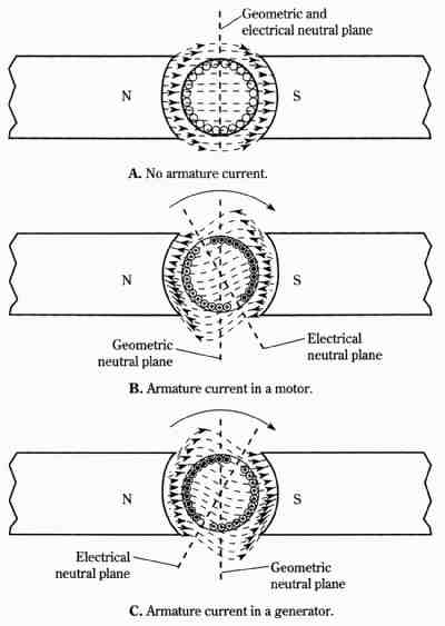
FIG. 4 Field distortion produced by current-carrying conductors in dc machines.
A. No armature current. Geometric and electrical neutral plane
B. Armature current in a motor. Electrical neutral plane
C. Armature current in a generator. Electrical neutral plane; Geometric neutral plane
It’s clear that considerably more is involved in commutation than the mere switching or reversing of current. And armature reaction—that is, the distortion of the main field by the magnetic field associated with the armature conductors—is not the only difficulty encountered. Another difficulty is the self-inductance of the armature. Even if an armature loop is shorted while progressing through main field flux that is parallel to its motion, considerable sparking can occur. It is true that no generator action is then taking place. But, because of the self-inductance of the armature, the current that had previously circulated in the shorted armature loop cannot be instantly extinguished. Thus, full advantage cannot be taken of the fact that the shorted armature loop does not cut field flux. In other words, what appears to be a neutral plane is not, as far as clean commutation is concerned.
The effect described is often lumped under the general heading of “armature re action.” However, I have clearly delineated two separate phenomena. Armature reaction has to do with the bending or distortion of the main field flux. Armature self-inductance has to do with the fact that armature current requires time to die down to zero after field flux is no longer being cut. The reason the two phenomena are frequently lumped under the heading “armature reaction” is that armature self-inductance behaves in some respects as if it were, indeed, additional armature reaction.
A straightforward remedy for armature reaction and armature self-inductance is an adjustable brush assembly. In a motor, the brushes must be shifted backwards from the direction of rotation in order to achieve clean commutation. The reverse is true in generators. In both cases, the shift of the brushes away from the geometric neutral plane is more than sufficient to avoid the effects of armature reaction alone. Additional brush displacement is required to allow time for the current delayed by armature self- inductance to approach zero. When clean commutation is thereby attained, the brush axis can be said to lie in the true electrical neutral plane of the main field.
Canceling armature reaction with compensating windings
The adjustable brush technique obviously has manufacturing and economic short comings. Its greatest disadvantage, however, is that a given brush adjustment yields optimum performance for only one armature current. This might not be considered overwhelmingly unfavorable for some applications, but in general, a remedy that is independent of current is desirable. Experiments have been conducted using electronically actuated servo controls to automatically maintain the brushes at optimum positions for clean commutation, despite wide variations in armature current. Al though it is too early to judge this approach, it appears suitable primarily for large machines. However, all things considered, it would be better to dispense with such mechanical motion.
An accepted technique for accomplishing near cancellation of armature reaction is shown in FIG. 5, where so-called compensating windings are placed in slotted faces of the main pole pieces. In this diagram, as well as in most of the dc motor and generator illustrations in this guide, two-pole structures are depicted. This is done for the sake of simplicity; practical machines often have two or more pairs of poles. Also, the main field poles are usually shown as being simple permanent magnets. Although the main field poles can be permanent magnets, they are more often electro magnets. And, unless stated otherwise, the windings on the main poles might be a relatively few turns of heavy wire that carry the full armature current, or they might be many turns of fine wire that are connected across the terminals of the armature. These two cases correspond to series- and shunt-type machines, respectively. Al though such machines have widely differing characteristics, a general discussion of commutation, armature reaction, and armature self-inductance is made easier if it is assumed that the way in which the main field is produced is not of primary importance. Thus, it would be distracting to show main field windings and their connections in FIG. 5A. Basically, it is desirable to focus attention on the way in which the po1 conductors tend to cancel the magnetic fields that the armature conductors would otherwise contribute to the air gap. In FIG. 5B, the motor is shown with a shunt field to emphasize that the compensating windings are an addition to an otherwise “normal” motor.
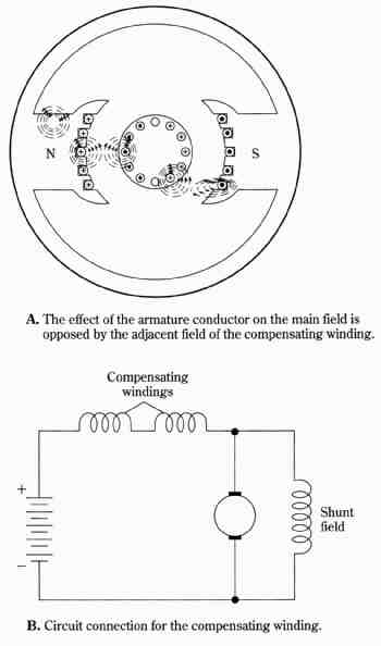
FIG. 5 The use of compensating windings for canceling armature reaction.
A. The effect of the armature conductor on the main field is opposed by the adjacent field of the compensating winding. [Compensating windings; Shunt field]. B. Circuit connection for the compensating winding