AMAZON multi-meters discounts AMAZON oscilloscope discounts
OBJECTIVES
• state the purpose of a dc voltage drop acceleration controller.
• explain the principle of operation of lockout relays in a dc voltage drop acceleration controller.
• list, in sequence, the steps in the operation of an acceleration controller.
• connect an acceleration controller to a dc motor.
Large dc motors must be accelerated in controlled steps. A series of resistors or tapped resistors connected to lockout relays can be used to provide uniform motor acceleration. Since the starting current of a motor is high, the voltages across the series starting resistors are high and the voltage across the motor armature is low. As the motor accelerates and the counter emf increases, the armature current and the voltage drop across the series starting resistors decrease. Lockout relays connected across these resistors are calibrated to short out the series starting resistors as the motor speeds up.
CIRCUIT FOR THE VOLTAGE DROP ACCELERATION CONTROLLER
The Lockout Relay
For this circuit, motor acceleration is divided into three steps due to the actions of three lockout relays. A lockout relay has two coils, as illustrated in 1. For each relay illustrated in 2, coil A is connected across the line and serves as the operating coil of the relay. Coil LA of each relay is connected across one starting resistor. Since there are three starting resistors, three lockout relays are used to provide three steps of acceleration. The voltage drop across the resistors is high enough during the starting period to prevent the main control coil A of each relay from closing the A contacts which shunt or bypass the starting resistors. This action is called lockout.
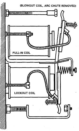
ill. 1 A lockout relay. (BLOWOUT COIL, ARC CHUTE REMOVED)
Starting the Motor
When the start button in figure 2 is pressed, the control relay M is energized. The main contacts 9-10 close and complete the armature circuit through the thermal element and the three resistors. The shunt field is connected across the line. Contacts 3—6 and 6—4 seal in the start button contact. Contacts 3—6 also energize coil 1A. The large value of starting current through the starting resistance produces a large voltage drop across each section of the starting resistance. As a result, there is a large voltage to the lockout coils 1 LA, 2 LA, and 3 LA and the accelerating contacts 1A, 2A, 3A are held open.
Contacts 4—6 are used to prevent coils 1A, 2A, and 3A from energizing when the start button is depressed. These coils receive power only when coil M is energized so they are not energized before coils 1 LA, 2LA, and 3 LA.
Acceleration
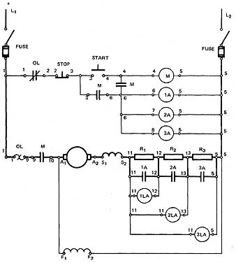
ill. 2 Elementary diagram for the dc voltage drop acceleration
controller.
As the motor accelerates, the counter emf increases in the armature and the armature current decreases. With reduced current in the lockout coil of the relay, the pull of the lockout coil on the relay armature is less than the pull of the operating coil 1A. Therefore, relay 1A closes and contacts 1A bypass resistor R1. Relay coil 2LA remains open due to the voltage drop across R2, while relay coil 3LA remains open due to the voltage drop across R3 and R4. As R1 is bypassed, the current again increases and the voltage drop across R2 is high enough to keep the contacts of relay 2A open. However, as the motor continues to accelerate, the armature current decreases and lockout coil 2LA allows relay 2A to close contacts 2A and bypass resistor R2.
Connecting the Motor across the Line
Resistor R3 is bypassed in the same manner as R1 and R2. The motor is accelerated to normal speed in three steps. It is connected directly across the line when resistor R3 is cut out.
Running Overload Protection
A sustained overload greater than the permissible percentage of the full-load current causes the thermal element to open overload contacts 1—2 which, in turn, causes coil M to become deenergized. Contacts 9-10 are then opened and the motor is shut down. Manual shut-down protection is obtained by pressing the stop button.
SUMMARY
The dc voltage drop acceleration controller can be used to provide definite steps of acceleration. The concept used is to electrically lock out the resistor shunting contacts. The large armature current operates a lockout portion of the relay and won't allow the shunting contacts to close until the armature current has decreased.
QUIZ
Select the correct answer or answers for each of the following statements.
1. High motor starting current will:
a. increase the field current.
b. decrease the speed.
c. increase the voltage drop across the starting resistors.
d. decrease the voltage drop across the starting resistors.
2. The voltage drop acceleration method of speed control is particularly suited to:
a. braking of motors.
b. starting small motors.
c. starting large motors in one step.
d. starting large motors in three steps.
3. Large dc motors are started with:
a. single-step acceleration.
b. multiple-step acceleration.
c. elementary counter emf controllers.
d. auxiliary motors.
4. The lockout relay has:
a. one main coil.
b. three coils.
c. one closing and one lockout coil.
d. two coils wound in series.
5. The main coil in a lockout relay is connected across the source and the lockout coil is energized by the:
a. counter emf.
b. voltage drop across the starting resistor.
c. total current in armature.
d. current in the field circuit.
6. The lockout coil of the lockout relay weakens and causes the relay contacts to close when the:
a. motor speed drops.
b. counter emf rises and reduces the motor current.
c. counter emf decreases.
d. starting resistance is cut out.
7. A decreasing starting current causes the lockout relay to:
a. cut in the starting resistance,
b. cut out the starting resistance.
c. increase the field resistance.
d. decrease the field resistance.
8. Motor circuit protection during the starting period is provided by the:
a. thermal unit.
b. branch fuses.
c. distribution line fuses.
d. motor circuit breaker.
9. A running load in excess of 150 percent of the full-load current causes the:
a. main line circuit to open before the control circuit.
b. control circuit to be opened,
c. speed to decrease.
d. Field rheostat to be bypassed.
10. The panel wiring is completed by referring to the:
a. relay symbols. c. conduit plan.
b. elementary diagram. d. motor schematic diagram.
STUDENT/LEARNER ACTIVITY
Complete the conduit plan ( 3) using the panel wiring diagram ( 4) as a reference.
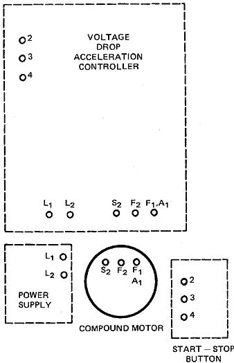
ill. 3 Conduit plan, external wiring for a dc voltage drop
acceleration controller. Voltage drop acceleration controller, start-stop
button, compound motor
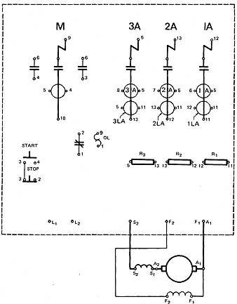
ill. 4 Panel wiring diagram for the dc voltage acceleration
controller with pushbuttons in the hinged cover.