AMAZON multi-meters discounts AMAZON oscilloscope discounts
OBJECTIVES
• describe the operation of a dc series lockout relay.
• list the steps in the operating sequence of a series lockout relay acceleration controller.

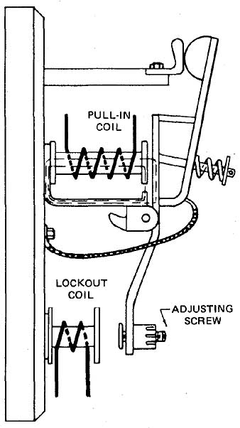
ill. 1 Series lockout relay: Note: In another type of relay,
the magnetic gap is changed by shims located in back of the coil, rather
than by an adjusting screw.
A series lockout relay with its two coils is illustrated in 1. The lockout coil prevents the relay contacts from closing during the period of high motor starting current.
The pull-in coil closes the relay contacts when the motor has accelerated and the starting current is reduced.
OPERATION OF THE SERIES LOCKOUT ACCELERATION CONTROLLER

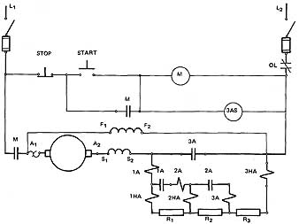
ill. 2 Elementary diagram for the series lockout acceleration
controller.
ill 2 is the elementary diagram of a controller which uses series lockout relays to produce the necessary time delay or step control in motor acceleration.
Coils 1 A, 2A, and 3A are the pull-in coils of the three relays, while coils 1 HA, 2HA, and 3HA are the lockout coils of the relays.
When the start button is pressed, coil M is energized, and the main contactor, M, (1) seals the bypass auxiliary contact around the start button, and (2) allows current to flow in the following sequence: from L1 through contact M, the motor armature, the series field, coil 1A, coil 1HA, resistors R1, R2 and R3 and coil 3HA to L2.
The large starting current through coil 1 HA produces a large magnetic effect in this coil. Since this effect is larger than that of coil 1A, the relay is held open due to the fact that the magnetic path of the pull-in coil has a small amount of iron. As a result, this coil becomes saturated at high values of current. The magnetic circuit of the lockout coil has a larger amount of iron and , therefore, does not tend to become saturated at a high current value.
As the motor accelerates and the starting current decreases, the pull of the lockout coil becomes less than the pull of the pull-in coil and contactor 1A closes. Resistor R1 and lockout coil 1HA are bypassed and thus increased current is allowed through lockout relay coils 2A and 2HA. A cycle of operation similar to that which occurred for relay 1A now takes place for relay 2A. The current path is now from L1 through M, the armature and series field, coil 1A, contact 1A, coils 2A and 2HA, resistors R2 and R3 and coil 3HA to L2. The large current through lockout coil 2HA produces more magnetic pull than is present at coil 2A with the result that contact 2A is held open.
Finally, as the motor accelerates, all resistors and relays are shunted out. This should immediately cause all relay contacts to drop out, except for the fact that coil 3AS is an auxiliary shunt coil which acts on contactor 3A. Coil 3AS is strong enough to hold contact 3A closed after it has been pulled into contact, but isn't strong enough to cause 3A to close its contacts without the aid of coil 3A.
When there is a heavier load on the motor, acceleration takes place over a longer period of time.
SUMMARY
The operation of the series lockout relay differs from the voltage drop relay. The lockout relay coil is in series with the pull-in coil. The magnetic fields are designed to pull the lockout coils first. As the current to the armature decreases, the lockout coil field is weakened and the shunting coils are allowed to pull the contacts shut, bypassing the armature resistors.
QUIZ
1. How is control relay M in the series lockout acceleration controller held in when the start button is released?
2. How does the lockout relay short out a starting resistor when the motor is accelerated?
3. What will happen if a break occurs in the coil of 3A?
4. A motor accelerates through two steps only. The speed is below normal and the motor voltage is low at the armature terminals. What is the probable cause of the problem?
5. What is the purpose of the 3AS coil of the lockout relay?