AMAZON multi-meters discounts AMAZON oscilloscope discounts
OBJECTIVES
• diagram the connections for a single-phase, three-wire secondary system.
• list the advantages of a three-wire service.
• describe what occurs when the neutral of a three-wire secondary system opens.
• explain why there is less copper loss for a three-wire system.
Most homes are wired for three-wire service. Since electric ranges and air conditioners are designed for three-wire operation, any home which is to be provided with these appliances must have three-wire service. The three wires terminate in the residence at the load center panel so that most individual circuits carried through the house are at 115 volts, thus eliminating the dangers with 230-volt circuits.
The double-wound transformer is used as the source for three-wire secondary distribution. One of the important advantages of a transformer is its ability to provide a three-wire circuit from the low-voltage secondary. A step-down transformer with a 2,300/ 230/115-volt rating is commonly used in residential installations.
The advantages of the use of three-wire service in general distribution systems include (1) a reduction in the cost of main feeders and sub-feeders, (2) the provision of 115-volt service for normal lighting circuits and 230-volt service for power and motor loads, and (3) the conservation of electrical energy by reducing watt loss in transmission.
ill. 1 is a schematic of a typical three-wire system. The secondary coils are connected in series and each coil is rated at 115 volts. The junction N between the two secondary Coils is usually grounded. This precaution provides some protection to an individual who may come into contact accidentally with a transformer that has faulty insulation. The line wire carried from this junction to the several loads is known as the neutral or identified conductor. The neutral wire generally carries less current than wires L1 and L2 except when the load is on one side only, that's L1 to N or L2 to N. The 230-volt motor load does not affect the current flowing in the neutral wire. The neutral is carried through the system as a solid conductor (not fused or switched). If the neutral opens, and the loads in the 115-volt circuits are greatly unbalanced, then these 115-volt circuits will be subjected to approximately 230 volts. The neutral is designed to carry not only the unbalanced current in the two 115-volt circuits, but also the entire load on any one side should all the load on the other side be cut off completely. This latter situation can occur if a fuse or circuit breaker suddenly opens either line. ill 1 shows the current distribution for the loads indicated.
OPEN NEUTRAL
As an example to show what occurs when the neutral of a three-wire system opens, assume that the lighting load in figure 1 is a pure resistive load.
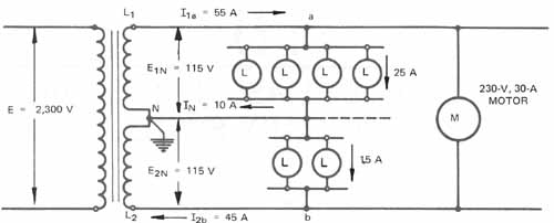
ill. 1: Schematic diagram of a three-wire system supplied from
a single-phase transformer
Thus, the group of four lamps has a resistance of: E/I = 115/25 or 4.6 ohms, and the group of two lamps has a resistance of: E/I = 115/15 = 7.666 ohms.
With the neutral open, these two groups combine as a series circuit with a resistance of 12.266 ohms connected across 230 volts. The current flow through this series circuit's:
E/R = 230/12.266 = 18.75 amperes
Then, according to the laws for a series circuit, the voltage across the 7.666-ohm group (two lamps) is equal to:
I x R = 18.75 x 7.666 = 143.74 volts and the voltage across the 4.6-ohm group (four lamps) is equal to:
I x R = 18.75 x 4.6 = 86.25 volts
(Remember that in a series circuit, the highest voltage appears across the highest value of resistance.) The lamps would probably burn out with this open neutral.
Sample Problem
Referring to figure 1, assume that the upper 115-volt load is 25 amperes, the lower load is 15 amperes, and the motor load is 30 amperes. If the power factor in all cases is unity (1), calculate the current
1. in line 1 - a.
2. in line 2 - b, and
3. in the neutral line N.
In addition, determine the power delivered
4. by transformer coil 1 - N,
5. by transformer coil N - 2, and
6. by the primary coil.
Finally, calculate the current
7. in the primary coil.
Solution
1. I(1 - a) = 25 +30 =55 amperes
2. I(2 - b) = 15 +30 =45 amperes
3. I(N) = 25 – 15 = 10 amperes
4. P(1-N)= 55x 115 =6,325watts
5. P(N - 2) = 45x 115 =5,175 watts
6. P(pri)= 6,325+5,175 =11,500 watts
7. I(pri) = 11,500/2,300 =5 amperes
The distribution transformers used in industrial plants or network substations for three-wire secondary systems are usually mounted on poles ( 2) or in transformer vaults. This type of transformer is equipped with three low-voltage bushings and the series connection is made inside the tank. The lower lines constitute the secondary three-wire systems.
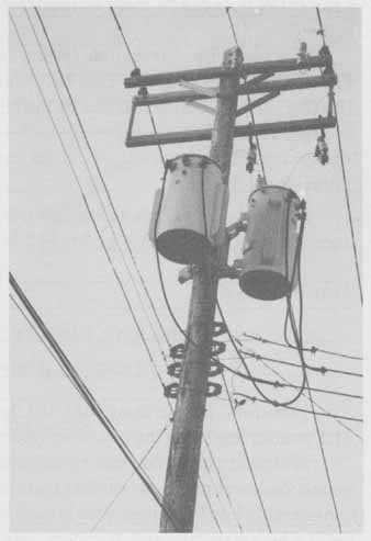
ill. 2: Pole top transformers used for distribution voltages
ECONOMICS OF THE THREE-WIRE SYSTEM FOR FEEDERS AND BRANCH CIRCUITS
Using the three-wire system of the previous problem as an example, the total load transmitted over the three wires is 11,500 W or 11.5 kW at a power factor of 100 percent. It is assumed that the motor load is provided with power factor correction. If single conductor-type TW wire is used from the transformer to the load, the following sizes are required.
Line 1 (55 amperes): No. 6 TW
Neutral (0.70 x 55 = 38.5): No. 8 TW
Line 2 (55 amperes): No. 6 TW
Although No. 8 TW wire is the actual size permitted for the neutral, a substitution of a No. 6 TW wire can be made so that three No. 6 lines are provided to simplify the installation.
If a two-wire distribution system is used for the same load, the total current is 11,500/115 = 100 amperes. Two No. 1 lines are required. If the transmission distance is
100 feet, then a comparison can be made of the weights of copper wire required for the two systems.
Three-Wire System
For a No. 6 TW line, the weight per 100 feet = 11.5 lb. Therefore, for 3 No. 6 TW lines, the total weight = 3 x 11.5 = 34.5 lb.
Two-Wire System
For a No. 1 line, the weight per 100 feet = 33 lb.
For 2 No. 1 lines, the total weight = 2 x 33 = 66 lb.
Therefore, for the same load, the three-wire system uses less copper (66 - 34.5 = 31.5 pounds less) than the two-wire system.
A similar conclusion can be reached by consulting a manufacturer’s price list and noting the lower prices for smaller size conductors. The copper losses in the line are also considerably less for a three-wire system for several reasons: the motor power is transmit ted at a higher voltage and , therefore, less current is required for a given load; the neutral carries no current when the two lighting circuits are balanced; the copper losses are much less because less wire and current are required. These line losses are of two types: (1) volt age drop (IR), and (2) wattage loss (I^2 x R)
SUMMARY
The three-wire single-phase system is the most common residential electrical ser vice. The three wires constitute a single phase of ac that's delivered to the home. The transformer secondary coil is tapped at the center point and grounded at that point to establish a ground reference. The power can then be divided into two 115 volt supplies and also be used as a 230 volt single phase for higher power consumption appliances. Care must be taken to solidly ground the neutral center-tapped-point because an open neutral conductor can cause severe damage.
QUIZ
1. Cite two reasons why power companies must supply three-wire service to residential occupancies.
2. How are the two secondary coils of a distribution transformer connected for three- wire service?
3. What are three advantages of a three-wire service as compared to a conventional two-wire service?
4. Why must the neutral line be left unfused?
5. How many circuits are provided in a three-wire secondary system?
6. What is the voltage rating of each circuit in question 5
Questions 7-9 are based on the following problem: a three-wire system has one lighting load of 40 amperes, one lighting load of 20 amperes, and a 230-volt motor load of 30 amperes.
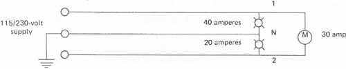
7. What is the current load in lines 1 and 2?
(1) _______ (2) ______
8. What is the current in N?
9. If the neutral is open, indicate the voltages of the lighting circuits. Show the work.
1-N _____
2-N _____
10. A three-wire, 120/240-volt circuit supplies the following:
One 120-volt, 1 0-watt lamp to line 1 and neutral, and
One 120-volt, 120-watt TV set to line 2 and neutral. (See diagram below.)
If the neutral opens while both the lamp and the TV set are operating, what will be the voltage at the lamp and the voltage at the TV set? (Assume power factor of unity.)
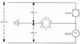
(lamp voltage) ______
(TV voltage) ________
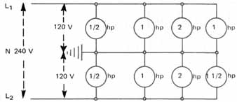
11. A manufacturer uses motors larger than 1 hp on 120 volts. Why does this require a three-wire secondary system?
12. Theoretically, how much horsepower is on the following unbalanced lines?
L1 ______ L2 ________ Neutral __________