AMAZON multi-meters discounts AMAZON oscilloscope discounts
Cont. from part d
Relay Control Logic
Digital signals are the language of modern day computers. Digital signals comprise only two states, which can be expressed as on or off. A relay can be considered digital in nature because it’s basically an on/off, two-state device.
It’s common practice to use relays to make logical control decisions in motor control circuits. The primary programming language for programmable logic controllers (PLCs) is based on relay control logic and ladder diagrams.
Control Circuit Inputs and Outputs
Most electrical control circuits can be divided into two separate sections consisting of an input and output. The input section provides the signals and includes such devices as manually operated switches and push buttons, automatically operated pressure, temperature, float, limit, and sensor switches, as well as relay contacts. In general, input signals initiate or stop the flow of current by closing or opening the control devices contacts.
The output section of the control circuit provides the action and includes such devices as contactors, motor starters, heater units, relay coils, indicator lights, and solenoids.
Outputs are load devices that directly or indirectly carry out the actions of the input section. The action is considered direct when devices such as solenoids and pilot lights are energized as a direct result of the input logic. The action is considered indirect when the coils in relays, contactors, and starters are energized. This is because these coils operate contacts, which actually control the load.
Motor control circuits may have one or more inputs controlling one or more outputs. A combination of input devices that either manually or automatically sense a condition-and the corresponding change in condition performed by the output device-make up the core of motor control. Ill.33 illustrates typical inputs and outputs of a control ladder diagram. The control logic for the circuit can be summarized as follows.
• Relay coil CR is energized when the on/off switch is closed and acts to close the CR-1 contact and open the CR-2 contact.
• For the horn to energize and sound, both the CR-1 contact and the limit switch must be closed.
• The solenoid is energized and operates whenever the CR-2 contact or float switch is closed.
• When the temperature switch closes, the contactor coil energizes and acts to close the C1 contact.
At the same time the circuit's completed to the red pilot light, switching it on.
• The heater unit's energized and operates whenever contact C1 is closed.
AND Logic Function
Logic is the ability to make decisions when one or more different factors must be taken into consideration. Control logic functions describe how inputs interact with each other to control the outputs and include AND, OR, NOT, NAND, and NOR functions. In electronic circuits these functions are implemented using digital circuits known as gates.
The AND logic function operates like a series circuit.
AND logic is used when two or more inputs are connected in series and they all must be closed in order to energize the output load. Ill.34 shows a simple application of the AND logic function. Most AND logic circuits use normally open input devices connected in series. In this application both the temperature switch and the float switch inputs must be closed to energize the solenoid output.
OR Logic Function
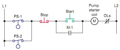
The OR logic function operates like a parallel circuit. OR logic is used when two or more inputs are connected in parallel and any one of the inputs can close to energize the output load. Ill.35 shows a simple application of the OR logic function. Most OR logic circuits use normally open input devices connected in parallel. In this circuit, any one of the two pushbutton inputs can close to energize the motor starter coil load.
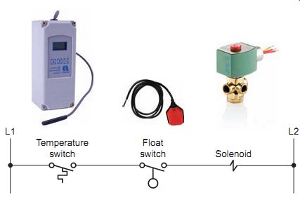
Ill.34 AND logic function. Temperature switch; Float switch Solenoid
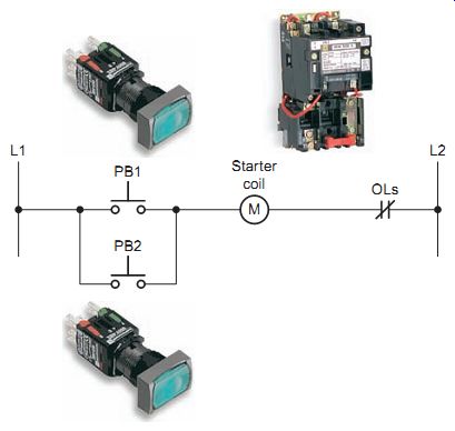
Ill. 35 OR logic function.
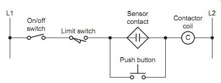
Ill. 36 AND/OR combination logic. Sensor contact; Contactor coil; On/off
switch; Limit switch
Combination Logic Functions
Control circuits often require more than one type of logic function when more complex decisions need to be made.
Ill. 36 shows an example of an AND/OR combination logic circuit. In this control application, the output is a contactor coil that's controlled by combined AND/OR logic functions. Both the on/off switch and limit switch in addition to the sensor contact or push button must be closed to energize the contactor coil.
NOT Logic Function
Unlike the AND logic and OR logic, the NOT logic function uses a single normally closed rather than a normally open input device. NOT logic energizes the load when the control signal is off. Ill.37 shows an example of the NOT logic function used to prevent accidental contact with live electrical connections. The normally closed safety switch operates by detecting the opening of guards such as doors and gates. Contacts of the normally closed safety switch are held open by the shut door. When the door is opened, the safety switch returns to its normally closed state and the trip solenoid of the circuit breaker is energized to remove all power from the circuit.
NAND Logic Function
NAND logic is a combination of AND logic and NOT logic in which two or more normally closed contacts are connected in parallel to control the load. Ill.38 shows an example of the NAND logic function used in the control circuit of a dual-tank liquid filling operation. The two tanks are interconnected and each is equipped with a float switch installed at the full level of the each tank. A three wire control circuit's used in addition to the two parallel connected float switches that provide the NAND logic of the circuit. With either or both tanks below the full level, momentarily depressing the start push button energizes the motor starter coil, turning on the pump motor. Both float switches must open for the motor to shut off automatically. The stop push button will shut down the process at any time.
NOR Logic Function NOR logic is a combination of OR logic and NOT logic in which two or more normally closed contacts are connected in series to control the load. Ill.39 shows an example of the NOR logic function used with three wire control to energize a motor starter. In this circuit the motor can be started from one location, but can be stopped from three locations. The three series-connected normally closed stop push buttons provide the NOR function of the circuit. Once the circuit's energized, if any one of the three stop push buttons is pressed, the starter coil M will deenergize.
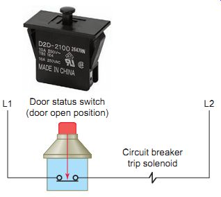
Ill.37 NOT logic function. Circuit breaker trip solenoid Door status
switch (door open position)
Ill.38 NAND logic function.
Circuit breaker trip solenoid Door status switch (door open position)
QUIZ:
1. Why can a relay be considered to be digital in nature?
2. What type of controller is based on relay control logic?
3. Compare the functions of the input and output sections of an electrical control circuit.
4. Define the term logic as it applies to electrical control circuits.
5. What configuration of contacts is logically equivalent to the AND function?
6. What configuration of contacts is logically equivalent to the OR function?
7. What type of contact is logically associated with the NOT function?
8. What configuration of contacts is logically equivalent to the NAND function?
9. What configuration of contacts is logically equivalent to the NOR function?
REPAIR/TROUBLESHOOTING SCENARIOS
1. An electromechanical relay is suspected of being bad. How would you go about checking the relay coil in and out of the circuit? How would you go about checking the relay contacts in and out of the circuit?
2. A solid-state relay with a control circuit rated for 5 V DC has a positive sign marked on one of the control terminal connections. What does this mean as far as the operation of the relay is concerned?
3. Assume the switching semiconductor within a solid-state relay becomes faulted as a short-circuit.
How would this affect the operation of the output circuit? How would the operation of the output circuit be affected if it became faulted as an open circuit?
4. The operation of an on-delay timer with a set of NOTC contacts is to be tested in-circuit by means of voltage measurements. Outline the procedures you would follow to determine if the circuit's operating properly.
5. Many alternating relays come equipped with a built-in switch that's used to manually force one motor of a dual motor system pump to run every time the circuit's actuated. Discuss in what troubleshooting instances this feature might be used.
DISCUSSION TOPICS / CRITICAL THINKING QUESTIONS
1. Why is the pickup voltage of an electromechanical relay normally higher than its dropout voltage?
2. During normal operation, solid-state relays generate more heat than equivalent electromagnetic types. Explain why the on-state resistance and off state current leakage of the switching semiconductor contribute to this.
3. A latching relay is sometimes referred to as a memory relay. Why?
4. Design and draw a combination logic circuit that includes the following logic functions connected to control a solenoid output load:
• Two push buttons connected to implement an AND logic function
• Three limit switches connected to implement an OR logic function
• A float switch connected to implement a NOT logic function