AMAZON multi-meters discounts AMAZON oscilloscope discounts
Cont. from part 1
Contactor Ratings, Enclosures, and Solid-State Types
NEMA Ratings
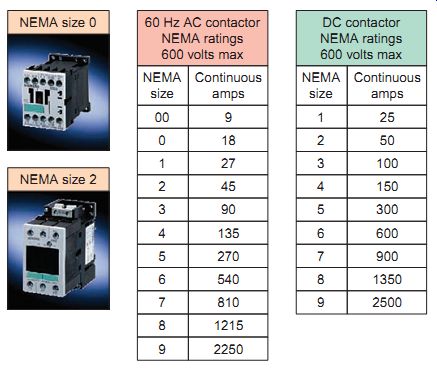
Ill. 21 NEMA contactor size guide.
The National Electric Manufacturers Association (NEMA) and the International Electrotechnical Commission (IEC) maintain guidelines for contactors. The NEMA standards for contactors differ from those of the IEC and it’s important to understand these differences.
A philosophy of the NEMA standards is to provide electrical interchangeability among manufacturers for a given NEMA size. Because the customer often orders a contactor by the current, motor horsepower, and voltage ratings, and may not know the application or duty cycle planned for the load, the NEMA contactor is designed by convention with sufficient reserve capacity to assure performance over a broad band of applications.
The continuous current rating and horsepower at the rated voltages categorize NEMA size ratings. NEMA contactor size guides for AC and DC contactors are shown in Ill. 21. Because copper contacts are used on some contactors, the current rating for each size is an 8-hour open rating-the contactor must be operated at least once every 8 hours to prevent copper oxide from forming on the tips and causing excessive contact heating. For contactors with silver to silver-alloy contacts, the 8-hour rating is equivalent to a continuous rating. The NEMA current rating is for each main contact individually and not the contactor as a whole.
As an example, a Size 00 three-pole AC contactor rated at 9 A can be used for switching three separate 9-A loads simultaneously. Additional ratings for total horsepower are also listed. When selecting always ensure that the contactor ratings exceed the load to be controlled. NEMA contactor sizes are normally available in a variety of coil voltages.
As the NEMA size number classification increases, so does the current capacity and physical size of the contactor. Larger contacts are needed to carry and break the higher currents, and heavier mechanisms are required to open and close the contacts.
EXAMPLE:
Problem: Use the table in Ill. 21 to determine the NEMA size of an AC contactor required for a 480-V heating element load with a continuous current rating of 80A.
Solution: According to the table, a size 2 contactor is rated for 45 A, while a size 3 is rated for 90 A. Since the load falls between these two values, the larger-size contactor must be used. The voltage requirement is satisfied because the controller can be used for all volt ages up to 600 V.
Magnetic contactors are also rated for the type of load to be utilized or for actual applications. Load utilization categories include:
• Nonlinear loads such as tungsten lamps for lighting (large hot-to-cold resistance ratio, typically 10:1 or higher; current and voltage in phase).
• Resistive loads such as heating elements for furnaces and ovens (constant resistance; current and voltage in phase).
• Inductive loads such as industrial motors and transformers (low initial resistance until the transformer becomes magnetized or the motor reaches full speed; current lags behind voltage).
• Capacitive loads such as industrial capacitors for power factor correction (low initial resistance as capacitor charges; current leads voltage).
IEC Ratings
Ill. 22 IEC type contactor.
IEC contactors, compared to NEMA devices, generally are physically downsized to provide higher ratings in a smaller package (Ill. 22). On average, IEC devices are 30 to 70 % smaller than their NEMA counterparts. IEC contactors are not defined by standard sizes, unlike NEMA contactors. Instead, the IEC rating indicates that a manufacturer or laboratory has evaluated the contactor to meet the requirements of a number of defined "applications." With knowledge of the application you can choose the appropriate contactor by defining the correct utilization category. This makes it possible to reduce contactor size, and therefore cost. The IEC rating system is broken down into different "utilization categories" that define the value of the current that the contactor must make, maintain, and break. The following category definitions are the most commonly used for IEC contactors:
AC CATEGORIES
AC-1: This applies to all AC loads where the power factor is at least 0.95. These are primarily non-inductive or slightly inductive loads.
AC-3: This category applies to squirrel-cage motors where the breaking of the power contacts would occur while the motor is running. On closing, the contactor experiences an inrush, which is 5 to 8 times the nominal motor current, and at this instant, the voltage at the terminals is approximately 20 % of the line voltage.
AC-4: This applies to the starting and breaking of a squirrel-cage motor during an inch or plug reverse. On energization, the contactor closes on an inrush current approximately 5 to 8 times the nominal current. On de-energization, the contactor breaks the same magnitude of nominal current at a voltage that can be equal to the supply voltage.
DC CATEGORIES
DC-1: This applies to all DC loads where the time constant ( L / R ) is less than or equal to 1 millisecond. These are primarily noninductive or slightly inductive loads.
DC-2: This applies to the breaking of shunt motors while they are running. On closing, the contactor makes the inrush current around 2.5 times the nominal rated current.
DC-3: This applies to the starting and breaking of a shunt motor during inching or plugging. The time constant is less than or equal to 2ms. On energization, the contactor sees current similar to that in category DC-2.
On de-energization, the contactor will break around 2.5 times the starting current at a voltage that may be higher than the line voltage. This would occur when the speed of the motor is low because the back emf is low.
DC-5: This applies to the starting and breaking of a series motor during inching or plugging. The time constant is less than or equal to 7.5 ms. On energization, the contactor sees about 2.5 times the nominal full-load current. On de-energization, the contactor breaks the same amount of current at a voltage that can be equal to the line voltage.
Contactor Enclosures
Enclosed magnetic contactors must be housed in an approved enclosure based on the environment in which they must operate to provide mechanical and electrical protection. Electrical codes mandate the type of enclosure to use. More severe environments require more substantial enclosures. Severe environmental factors to be considered include:
• Exposure to damaging fumes.
• Operation in damp places.
• Exposure to excessive dust.
• Subject to vibration, shocks, and tilting.
• Subject to high ambient air temperature.
There are two general types of NEMA enclosures: nonhazardous-location enclosures and hazardous-location enclosures. Nonhazardous-location enclosures are further subdivided into the following categories:
• General-purpose (least costly)
• Watertight
• Oil tight
• Dust-tight
Hazardous-location enclosures are extremely costly, but they are necessary in some applications. Hazardous-location, explosion-proof enclosures involve forged or cast material and special seals with precision-fit tolerances. The explosion-proof enclosures are constructed so that an explosion inside won’t escape the enclosure. If an internal explosion were to blow open the enclosure, a general-area explosion and fire could ensue. Hazardous location enclosures are classified into two categories:
• Gaseous vapors (acetylene, hydrogen, gasoline, etc.).
• Combustible dusts (metal dust, coal dust, grain dust, etc.).
All industrial electrical and electronic enclosures must conform to standards published by NEMA to meet the needs of location conditions. Ill. 23 shows typical NEMA enclosure types including:
NEMA Type 1 -general-purpose type, which is the least costly, and used in a location where unusual service conditions don’t exist.
NEMA Type 4 and 4X- Watertight and dust-tight.
NEMA Type 12 -Provides a degree of protection from noncorrosive dripping liquids, falling dirt, and dust.
NEMA Type 7 and 9 -Designed for use in hazardous locations.
Although the enclosures are designed to provide protection in a variety of situations, the internal wiring and physical construction of the device remains the same.
Consult the National Electrical Code (NEC) and local codes to determine the proper selection of an enclosure for a particular application.
The IEC provides a system for specifying the enclosures of electrical equipment on the basis of the degree of protection provided by the enclosure. Unlike NEMA, IEC does not specify degrees of protection for environmental conditions such as corrosion, rust, icing, oil, and coolants. For this reason, IEC enclosure classification designations cannot be exactly equated with NEMA. The table at top of page 148 provides a guide for converting from NEMA enclosure type numbers to IEC enclosure classification designations.
The NEMA types meet or exceed the test requirements for the associated IEC classifications; for this reason the table shouldn't be used to convert from IEC classifications to NEMA types and the NEMA to IEC conversion should be verified by test.
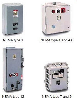
Ill. 23 Typical contactor enclosure types. NEMA type 1; NEMA type 12 NEMA type
7 and 9; NEMA type 4 and 4X
NEMA enclosure type number | IEC enclosure designation
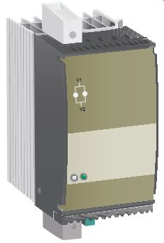
Ill. 24 Single-pole solid-state contactor.
Ill.
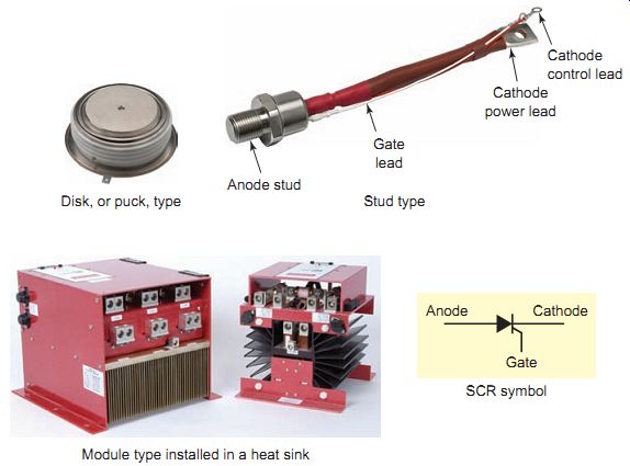
25 Silicon controlled rectifier (SCR) switching semiconductor.
Anode Cathode Gate SCR symbol Module type installed in a heat sink Stud type Disk, or puck, type Anode stud Cathode control lead Gate lead Cathode power lead
Solid-State Contactor
Solid-state switching refers to interruption of power by non-mechanical electronic means. Ill. 24 shows a single-pole AC solid-state contactor that uses electronic switching. In contrast to a magnetic contactor, an electronic contactor is absolutely silent, and its "contacts" never wear out. Static contactors are recommended in applications that require a high switching frequency, such as heating circuits, dryers, single- and three-pole motors, and other industrial applications.
The most common high-power switching semi-conductor used in solid-state contactors is the silicon controlled rectifier (SCR). An SCR is a three-terminal semiconductor device (anode, cathode, and gate) that acts like the power contact of a magnetic contactor. A gate signal, instead of an electromagnetic coil, is used to turn the device on, allowing current to pass from cathode to anode. Ill. 25 shows three types of SCR construction styles designed for higher-current applications: the disk (also known as puck type), stud mount, and module. Flexible-lead stud-mounted SCRs have a gate wire, a flexible cathode lead, and a smaller cathode lead that's used only for control purposes. The heat generated by the SCR must be dissipated; thus all contactors have some means to cool the SCR. Typically an aluminum heat sink, with fins to increase the surface area, is used to dissipate this energy to air.
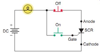
Ill. 26 SCR testing circuit.
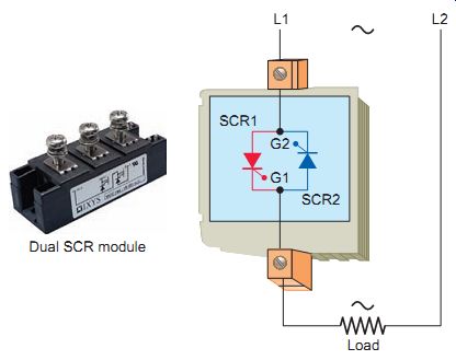
Ill. 27 SCR connection for single-phase contactor. Dual SCR module
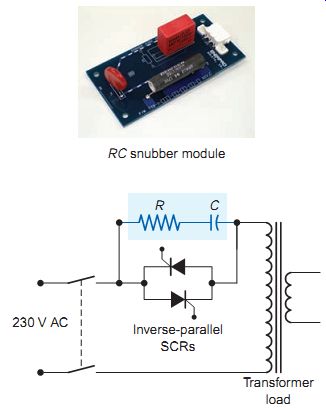
Ill. 28 SCR snubber circuit. RC snubber module; Inverse-parallel SCRs;
Transformer load.
The SCR, like a contact, is in either the on state (closed contact) or the off state (open contact). SCRs are normally off switches that can be triggered on by a small current pulse into the gate electrode. Once turned on (or triggered), the component then stays in the conducting state even when the gate on signal is removed. It returns to the off (blocking) state only if the anode-to-cathode current falls below a certain minimum or if the direction of the current is reversed. In this respect, the SCR is analogous to a latched contactor circuit-once the SCR is triggered, it will stay on until its current decreases to zero.
The SCR testing circuit shown in Ill. 26 is practical both as a diagnostic tool for checking suspected SCRs and as an aid to understanding how they operate. The operation of the circuit can be summarized as follows:
• A DC voltage source is used for powering the circuit, and two pushbutton switches are used to latch and unlatch the SCR, respectively.
• Momentarily closing the on push button connects the gate to the anode, allowing current to flow from the negative terminal of the battery, through the cathode-gate junction, through the switch, through the bulb, and back to the battery.
• This gate current should cause the SCR to latch on, allowing current to go directly from cathode to anode without further triggering through the gate.
• Momentarily opening the normally closed off push button interrupts the current flow to the SCR and bulb. The light turns off and remains off until the SCR is triggered back into conduction.
• If the bulb lights at all times, this is an indication that the SCR is shorted.
• If the bulb fails to light when the SCR is triggered into operation, this is an indication that the SCR is faulted open.
Since an SCR passes current in one direction only, two SCRs are necessary to switch single-phase AC power. The two SCRs are connected inverse-parallel (back-to-back), as shown in Ill. 27: one to pass current during the positive half-cycle and the other during the negative half cycle. Half the current is carried by each SCR, and sinusoidal AC current flows through the resistive load R when gates G1 and G2 are fired at 0 degrees and 180 degrees of the input, respectively.
Inductive loads and voltage transients are both seen as problem areas in solid-state AC contactor control because they could falsely trigger an SCR into conduction. For this reason, for driving an inductive load, a snubber circuit's used to improve the switching behavior of the SCR. Ill. 28 shows an electronic contactor, with a simple RC snubber circuit used to control an inductive transformer load. The snubber circuit consists of a resistor and capacitor wired in series with each other and placed in parallel with the SCRs. This arrangement suppresses any rapid rise in voltage across the SCR to a value that won’t trigger it.
The abrupt switching of an SCR, particularly at higher current levels, can cause objectionable transients on the power line and create electromagnetic interference (EMI).
By electrically switching an SCR on at the AC sine wave zero crossing point, it remains on through the half cycle of the sine wave and turns off at the next zero crossing. In this scheme, known as zero-i red control, the SCR is turned on at or nearly at the zero crossing point so that no current is being switched under load. The result is virtually no power line disturbances or EMI generation.
QUIZ:
1. Name the two major associations that maintain standard guidelines for contactors.
2. What three parameters are listed for each NEMA contactor size rating?
3. Use the NEMA contactor size guide to determine the NEMA size DC contactor required for a 240-V load with a continuous current rating of 80 A.
4. List four types of contactor load utilization categories.
5. Compare NEMA- and IEC-rated contactors with regard to
a. physical size.
b. the way in which they are rated.
6. Why are contactors mounted in an enclosure?
7. List the four categories of nonhazardous-location contactor enclosures.
8. Describe how explosion-proof contactor enclosures are constructed.
9. What does solid-state switching of contactors refer to?
10. For which type of switching operations are solid state static contactors best suited? Why?
11. Answer the following with reference to high-powered SCR switching semiconductors used in solid state contactors:
a. Which circuit of the SCR is connected in series with the load, like the power contacts of a magnetic contactor?
b. To which circuit of the SCR is the control signal that triggers the device into conduction applied?
c. In what way is the operation of an SCR analogous to that of a latched contactor circuit?
d. What effect can inductive loads and voltage transients have on the normal operation of an SCR?
e. Describe the method commonly used to dissipate the heat generated by an SCR.
Motor Starters
Magnetic Motor Starters
The basic use for the magnetic contactor is for switching power in resistance heating elements, lighting, magnetic brakes, and heavy industrial solenoids. Contactors can also be used to switch motors if separate overload protection is supplied. In its most basic form, a magnetic motor starter (Ill. 29) is a contactor with an overload protective device, known as an overload relay (OL), physically and electrically attached. The overload protective device protects the motor from overheating and burning up. Normally magnetic starters come equipped with some manufacturer installed control wiring, which may include:
• A wire connected from the overload relay contacts to the starter coil
• A wire connected from the other side of the starter coil to the holding contacts
• A wire connected from L2 to the other side of the overload relay contacts (note that this wire must be removed when a control transformer is used)
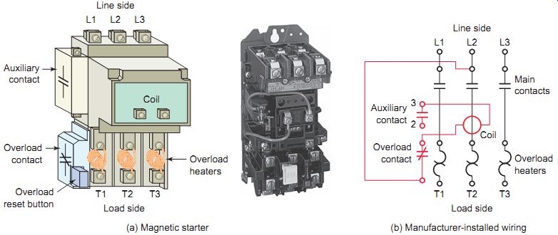
Ill. 29 Magnetic motor starter. (a) Magnetic starter; (b) Manufacturer-installed
wiring T1 T3 T2 Auxiliary contact Overload contact Overload heaters Overload
reset button L1 L2 Line side L3 Load side Coil
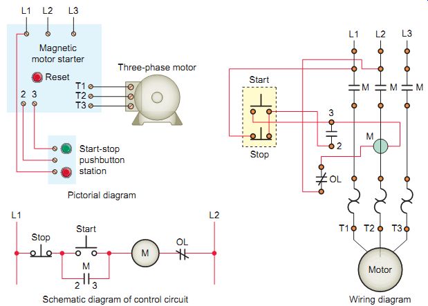
Ill. 30 Magnetic motor starter with separately mounted start-stop pushbutton
station. Magnetic motor starter; Pictorial diagram; Start-stop pushbutton
station
In their simplest and most widely used form, magnetic motor starters consist of a two-, three-, or four-pole magnetic contactor and an overload relay mounted in a suitable enclosure. Enclosures are essentially boxes that "enclose" motor control devices such as contactors, motor starters, and push buttons. They may be of general-purpose sheet metal construction, dust-tight, water-tight, or explosion resisting, or whatever may be required by the installation to protect motor control equipment and people. Start and stop push buttons may be mounted in the cover of the enclosure.
A separately mounted start/stop pushbutton station may also be used, in which case only the reset button would be mounted in the cover, as illustrated in Ill. 30. Starters are also built in skeleton form, without enclosure, for mounting in a motor control center or control panel on a machine. The control circuit of a magnetic motor starter is very simple. It involves only energizing the starter coil when the start button is pressed and de-energizing it when the stop button is pressed or when the overload relay trips.
Motor Overcurrent Protection
Motor branch circuits can be broken down into several major NEC requirements for motor installations, as illustrated in Ill. 31. They include:
• Motor circuit and controller disconnecting means
• Motor branch short-circuit and ground-fault protection
• Motor controller and overload protection
• Sometimes motor disconnecting means, often referred to as the "at the motor" disconnecting means
When an AC motor is first energized, a high inrush of current occurs. During the initial half-cycle, this inrush current is often 20 times the normal full-load current. After the first half-cycle the motor begins to rotate and the starting current subsides to 4 to 8 times the normal current for several seconds. As a motor reaches running speed, the current subsides to its normal running level. Because of the inrush current, motors require special overload protective devices that can withstand the temporary overloads associated with starting currents and yet protect the motor from sustained overloads.
Motor starting characteristics make motor protection requirements different from those for other types of loads.
When providing overcurrent protection for most circuits, we use a fuse or circuit breaker that combines overcurrent protection with short-circuit and ground-fault protection. Motor overcurrent protection is normally provided by separating the overload protection devices from the short-circuit and ground-fault protection devices, as illustrated in Ill. 32.
In addition the NEC also requires a disconnect means.
Motor overcurrent protection can be summarized as follows:
• Short-circuit and ground-fault motor protection. Branch and feeder fuses and circuit breakers protect motor circuits against the very high current of a short circuit or a ground fault. Fuses and circuit breakers connected to motor circuits must be capable of ignoring the initial high inrush current and allow the motor to draw excessive current during start-up and acceleration.
• Overload protection. Overload devices are intended to protect motors, motor control apparatus, and motor-branch circuit conductors against excessive heating due to motor overloads and failure to start. Motor overload may include conditions such as a motor operating with an excessive load or a motor operating with low line voltages or, on a three-phase motor, a loss of a phase. The motor overload devices are most often integrated into the motor starter.
The basic difference between a contactor and motor starter is the addition of overload relays as shown in Ill. 33. Contactor use is restricted to fixed lighting loads, electric furnaces, and other resistive loads that have set cur rent values. Motors are subject to high starting currents and periods of load, no-load, short duration overload, and so on. They must have protective devices with the flexibility required of the motor and driven equipment. The purpose of overload protection is to protect the motor windings from excessive heat resulting from motor overloading. The motor windings won’t be damaged when overloaded for a short period of time. If the overload should persist, however, the sustained increase in current should cause the overload relay to operate, shutting off the motor.
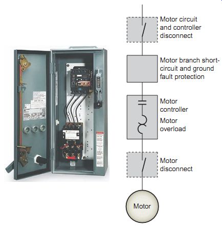
Ill. 31 Major functional blocks for motor operation.
Motor circuit and controller disconnect; Motor branch short-circuit and ground fault protection; Motor controller; Motor overload; Motor disconnect; Motor
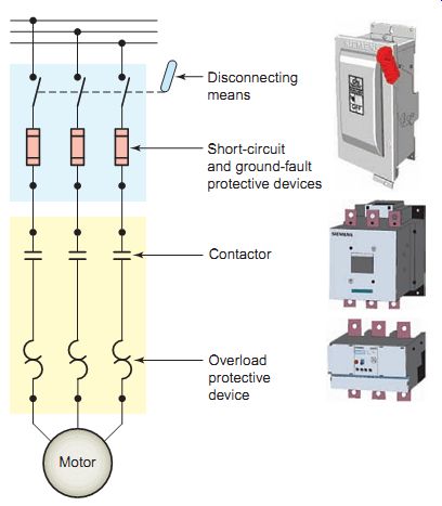
Ill. 32 Motor overcurrent protection. Contactor Short-circuit and ground-fault
protective devices Disconnecting means Motor Overload protective device
Motor Overload Relays
Overload relays are designed to meet the special protective needs of motor control circuits. Overload relays:
• Allow harmless temporary overloads (such as motor starting) without disrupting the circuit
• Will trip and open a circuit if current is high enough to cause motor damage over a period of time
• Can be reset once the overload is removed
Overload relays are rated by a trip class, which defines the length of time it will take for the relay to trip in an over load condition. The most common trip classes are Class 10, Class 20, and Class 30. A Class 10 overload relay, E.g. , has to trip the motor off line in 10 seconds or less at 600 % of the full-load amperes (which is usually sufficient time for the motor to reach full speed). The class designation is an important consideration in applying OL relays in motor-control circuits. E.g. , a high-inertia industrial load may require a Class 30 over load relay that trips in 30 seconds rather than a Class 10 or 20.
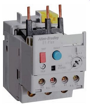
Normally overload protection devices have a trip indicator built into the unit to indicate to the operator that an overload has taken place. Overload relays can have either a manual or an automatic reset. A manual reset requires operator intervention, such as pressing a button, to restart the motor. An automatic reset allows the motor to restart automatically, usually after a cooling-off period; this allows the motor time to cool. After an over load relay has tripped, the cause of the overload should be investigated. Motor damage can occur if repeated resets are attempted without correcting the cause of the overload relay tripping. Ill. 34 shows a three pole Class 10 overload relay that features a manual or automatic resetting mode selection. The nominal current setting allows the relay to be set to the full-load current shown on the motor rating plate and can be adjusted to the desired trip point.
External-overload protection devices, which are mounted in the starter, attempt to monitor the heating and cooling of a motor by sensing the current flowing to it. The current drawn by the motor is a reasonably accurate measure of the load on the motor and thus of its heating. Overload relays can be classified as thermal, magnetic, or electronic.
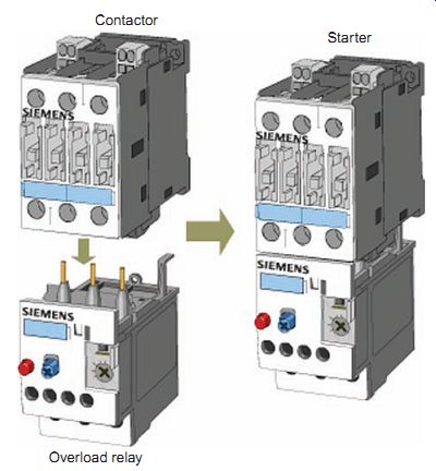
Ill. 33 The basic difference between a contactor and motor starter is
the addition of overload relays. Starter Contactor; Overload relay
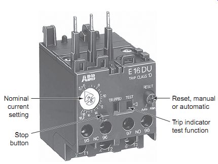
Ill. 34 Overload relay trip indicator. Nominal current setting; Trip
indicator test function; Reset, manual or automatic; Stop button
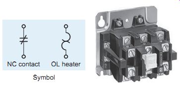
Ill. 35 Thermal overload relay.
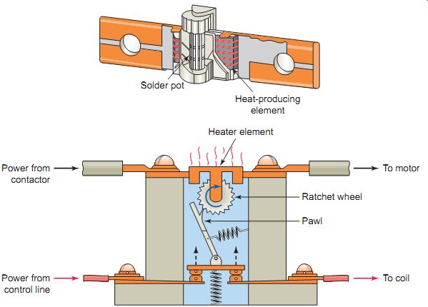
Ill. 36 Melting alloy-type thermal overload relay. Solder pot; Heat-producing
element Heater element Ratchet wheel Pawl Power from contactor Power from
control line; to motor; to coil
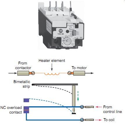
Ill. 37 Bimetallic type of thermal overload relay. To coil; Heater element;
From contactor; To motor; NC overload contact; Bimetallic strip; From
control line
THERMAL OVERLOAD RELAYS
A thermal overload relay uses a heater connected in series with the motor supply. Current flowing from the motor contactor to the motor passes through the motor overload heaters (one per phase), which are mounted in the overload relay block. Each thermal overload relay (Ill. 35) consists of the main overload block, which houses the contacts, a tripping mechanism with reset button, and inter changeable heaters sized for the motor being protected.
The amount of heat produced increases with supply cur rent. If an overload occurs, the heat produced causes a set of contacts to open, interrupting the circuit. Installing a different heater for the required trip point changes the tripping current. This type of protection is very effective because the heater closely approximates the actual heating within the windings of the motor and has a thermal "memory" to prevent immediate reset and restarting.
Thermal overload relays can be further subdivided into two types: melting alloy and bimetallic. The melting alloy type, illustrated in Ill. 36, utilizes the principle of heating solder to its melting point. It consists of a heater coil, eutectic alloy, and mechanism to activate a tripping device when an overload occurs. The term eutectic means easily melted. The eutectic alloy in the heater element is a material that goes from a solid to liquid state without going through an intermediate putty stage. The operation of the device can be summarized as follows:
• When the motor current exceeds the rated value, the temperature will rise to a point where the alloy melts; the ratchet wheel is then free to rotate, and the contact pawl moves upward under spring pres sure, allowing the control circuit contacts to open.
• After the heater element cools, the ratchet wheel will again be held stationary and the overload contacts can be reset.
The bimetallic type of thermal overload relay uses a bimetallic strip made up of two pieces of dissimilar metal that are permanently joined by lamination. The operation of the device can be summarized as follows:
• Heating the bimetallic strip causes it to bend because the dissimilar metals expand and contract at different rates.
• Overload heating elements connected in series with the motor circuit heat the bimetal tripping elements in accordance to the motor load current.
• The movement/deflection of the bimetallic strip is used as a means of operating the trip mechanism and opening the normally closed overload contacts.
With a thermal overload relay, the same current that goes to the motor coils (causing the motor to heat) also passes through the thermal elements of the overload relays. The thermal element is connected mechanically to an NC overload (OL) contact (Ill. 38). When an excessive current flows through the thermal element for a long enough time period, the contact is tripped open. This contact is connected in series with the control coil of the starter. When the contact opens, the starter coil is deenergized. In turn, the starter's main power contacts open to disconnect the motor from the line.
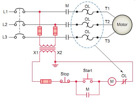
Ill. 38 Thermal overload relay circuit operation.
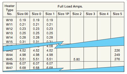
Ill. 39 Typical motor overload heater selection chart.
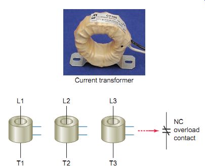
Ill. 40 Electronic overload relays use current transformers to sense
motor current. Current transformer
Ill. 41 Electronic solid-state overload relay.
Damage due to overloads accounts for most motor failures. Selecting the proper heater size for thermal OL relays is critical for ensuring maximum motor protection. Overload heaters for continuous-duty motors are selected from manufacturer's tables or charts, similar to that illustrated in Ill. 39, and based on compliance with Section 430.20 of the NEC. Selection tables normally list OL heaters according to motor full-load current (FLC). The lists show the range of motor cur rents with which they should be used. These may be in increments of from 3 to 15 % of FLC. The smaller the increment, the closer the selection can be to match the motor to its actual work.
When the overload heater element is rated according to the motor FLC, the calculations required by the NEC to determine the necessary level of protection have already been completed. E.g. , an OL heater rated at 10 A in the selection table is intended for use with a motor that has a 10-A FLC. Typically, it’s assumed that the motor has a service factor of 1.15 or greater and a temperature rise not over 40° C, which allows the motor to be protected up to 125 % of the nameplate FLC rating. NEMA standards permit classifying OL heater elements in this manner, but require the manufacturer to provide conversion factors for selecting devices to protect motors that have a service factor less than 1.15 or a temperature rise over 40° C (104° F).
Thermal overload relays react to heat, regardless of the origin of the heat. Ambient temperatures can greatly affect the tripping time of a thermal overload relay. Cooler temperatures increase tripping times, while warmer temperatures decrease tripping times. Ambient compensated bimetal overload relays are designed to overcome this problem. A compensating bimetal strip is used along with the primary bimetal. As the ambient temperature changes, both bimetals will bend equally and the overload relay won’t trip.
ELECTRONIC OVERLOAD RELAYS
Unlike electromechanical overload relays that pass motor current through heating elements to provide an indirect simulation of motor heating, an electronic over load relay measures motor current directly through a current transformer . It uses a signal from the current transformer, as illustrated in Ill. 40, along with precision solid-state measurement components to pro vide a more accurate indication of the motor's thermal condition. Electronic circuitry calculates the average temperature within the motor by monitoring its starting and running currents. When a motor overload occurs the control circuit operates to open the NC overload relay contacts.
Ill. 41 shows an electronic overload relay designed to be mounted in a two-component (contactor and OL relay) starter assembly. Heaters are not used; full-load current is set with a dial. This particular electronic overload relay is adjustable for a full-load motor current of from 1 to 5 A. This wide 5:1 adjustment range results in the need for half as many catalog numbers as the bimetallic alternative in order to cover the same current range. A separate phase loss detection circuit incorporated into the overload relay allows it to respond quickly to phase loss conditions. The self-enclosed latching trip relay contains a set of isolated NC and NO contacts that provide trip and reset functions for control circuits. Whenever an overload motor condition is sensed, these contacts change state and trigger a control circuit that interrupts current flow to the motor. The low energy consumption of the electronic design minimizes temperature rise issues inside control cabinets.
Dual- in-line package (DIP) switch settings allow the selection of trip class (10, 15, 20, or 30) and the reset mode (manual or automatic).
Advantages of solid-state electronic overload relays over thermal-overload types include the following:
• No buying, stocking, installing, or replacing of heater coils.
• Reduction in the heat generated by the starter.
• Energy savings (up to 24 W per starter) through the elimination of heater coils
• Insensitivity to temperature changes in the surrounding environment.
• High repeat trip accuracy (±2 %).
• Easily adjustable to a wide range of full-load motor currents.
Although both bimetal and eutectic trip mechanisms are still used, solid-state overload relays are more popular for the majority of newer motor control installations. Despite the differences between NEMA and IEC motor controls, the two types have a major similarity- the solid-state overload relay. There is little difference between solid-state overload relays used for either type.
In some applications, the same solid-state overload relay can be used in NEMA and in IEC units, leaving the contactor and enclosure the main differences between the two.
Another form of the electronic overload relay is the microprocessor-based type often found in adjustable-speed drive controllers. In addition to motor overload protection, other protective features may include over-temperature, instantaneous overcurrent, ground fault, phase loss/phase reversal/phase unbalance (both voltage and current), overvoltage, and undervoltage protection. Some units can tabulate the number of starts per programmed unit of time and lock out the starting sequence, preventing inadvertent excessive cycling.
DUAL-ELEMENT FUSES
Dual-element (time-delay) fuses, when properly sized, provide both overload and fault protection. This type of fuse contains dual fuse elements with both thermal and instantaneous trip features that allow the high motor starting current to flow for a short time without blowing the fuse. Ill. 42 shows the construction of a dual-element fuse. The operation of a dual-element fuse can be summarized as follows:
• Under sustained overload conditions, the trigger spring fractures the calibrated fusing alloy of the overload element, releasing the connector. The insets in Ill. 42 represent a model of the over load element before and after.
• A short-circuit fault causes the restricted portions of the short-circuit element to vaporize, and arcing commences. The special granular, arc-quenching filler material quenches the arcs, creating an insulating barrier that forces the current flow to zero.
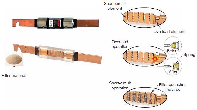
Ill. 42 Dual-element fuse.
Short-circuit element Overload element Overload operation Short-circuit operation Filler quenches the arcs Filler material After Before Spring
QUIZ:
1. Name the two basic components of a magnetic motor starter.
2. What manufacturer-installed control wiring may come with the starter?
3. List four common types of motor starter enclosures.
4. Identify four major NEC requirements for motor installations.
5. Explain how motor overload protection devices function to protect the motor.
6. In what manner is motor overcurrent protection normally provided?
7. Outline three important operating characteristics of overload relays.
8. Assume an overload relay is rated for trip Class 20. What exactly does this mean?
9. Compare the operation of the manual reset and automatic reset overload relays.
10. List three ways in which motor overload relays are classified.
11. How do thermal overload relays provide an indirect monitoring of motor heating?
12. Compare how the tripping device is activated in a melting alloy- (eutectic) and a bimetal-type thermal overload relay.
13. List four major factors to be considered when selecting the proper heater size for a motor thermal overload relay.
14. How is motor current sensed in an electronic over load relay?
15. List five advantages of electronic overload relays over thermal overload relay types.
16. Explain the operating principle of a dual-element (time-delay) fuse.
REPAIR/TROUBLESHOOTING EXAMPLES:
1. Identify possible causes or things to investigate for each of the following reported problems with a magnetic contactor or motor starter.
a. Noisy coil assembly.
b. Coil failure.
c. Excessive wear on electromagnet.
d. Overheating of the blowout coil.
e. Pitted, worn, or broken arc chutes.
f. Failure to pick up.
g. Short contact life.
h. Broken flexible shunt.
i. Failure to drop out.
j. Insulation failure.
k. Failure to break arc.
l. An overload that trips on low current.
m. Failure to trip (motor burnout).
n. Failure to reset.
2. A magnetic contactor coil rated for 24 V AC is incorrectly replaced with an identical physical size coil rated for 24 V DC. How might this affect the operation of the contactor or starter?
3. Solid-state SCR switching contactor modules may become faulted as short circuits or open circuits. Discuss symptoms that might be associated with each type of failure.
4. One of three starter thermal overload heater elements has become open-circuited because of overheating and is to be replaced. Why is it recommended that the set of three rather than the single heater element be replaced?
5. List the things to investigate in determining the cause of excessive tripping of a motor overload device.
DISCUSSION and CRITICAL THINKING ISSUES:
1. The key to understanding conductor and motor protection is to know the meaning of ground fault, short-circuit fault, and overload. Demonstrate your understanding of these terms by citing motor circuit examples of each.
2. Explain how electronic overload relays protect against single phasing.
3. Why are IEC contactors and starters much smaller in size than their NEMA counterparts?
4. Identify the different types of contacts found on a magnetic motor starter and describe the function each performs.
5. Search the Internet for motor starter enclosures and identify the a NEMA type that would be suitable for each of the following environments:
a. In a paint booth
b. In a boiler room
c. At a grain feed mill
d. Inside a plant for lathe controls
6. Inherent motor protection devices are located in the motor housing or mounted directly to the motor and accurately sense the heat being generated by the motor. Draw the schematic for a standard three-wire control circuit showing this type of device integrated into the control circuit.