AMAZON multi-meters discounts AMAZON oscilloscope discounts
GOALS:
- 1. Familiarize yourself with the basic uses for a contactor.
- 2. Explain how arc suppression is applied to contacts.
- 3. Discuss the major factors in selecting the size of a contactor and type of enclosure.
- 4. Explain the difference between a contactor and a motor starter.
- 5. Explain the function and operation of motor overload relays.
- 6. Compare NEMA and IEC types of contactors and starters.
- 7. Understand the operation of a solid-state contactor and starter.
Motor starters and contactors are used for switching electric power circuits. Both use a small amount of control current to energize or deenergize the loads connected to them. This section examines how contactors and motor starters are used in the control of non-motor and motor loads.
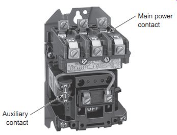
Ill. 1 Typical magnetic contactor. Main power contact; Auxiliary contact
Magnetic Contactor
The National Electrical Manufacturers Association (NEMA) defines a magnetic contactor as a magnetically actuated device for repeatedly establishing or interrupting an electric power circuit. The magnetic contactor is similar in operation to the electromechanical relay. Both have one important feature in common: contacts operate when the coil is energized. Generally, unlike relays, contactors are designed to make and break electric power circuit loads in excess of 15 A without being damaged. Ill. 1 shows a typical NEMA magnetic contactor used for switching AC motor loads for which overload protection isn't required or pro vided separately. In addition to the three power contacts, one normally open auxiliary hold-in contact is provided to accommodate three-wire pushbutton control.
There are two circuits involved with the operation of a magnetic contactor: the control circuit and the power circuit. The control circuit's connected to the coil, and the power circuit's connected to the main power contacts.
The operating principle of a three-pole magnetic contactor is illustrated in Ill. 2. When voltage is applied to the terminals of the coil, the current flows through the coil, creating a magnetic field. The coil, in turn, magnetizes the stationary iron frame, turning it into an electromagnet.
The electromagnet draws the armature toward it, pulling the movable and stationary contacts together. Power then flows through the contactor from the line side to the load side. Generally a contactor is available in two-, three-, or four-pole contact configurations.
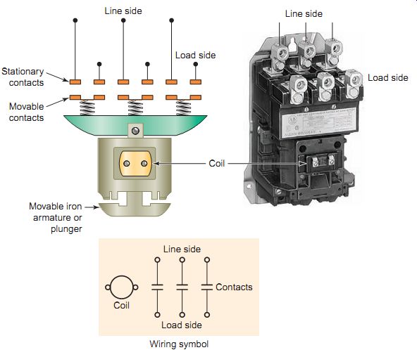
Ill. 2 Three-pole magnetic contactor. Wiring symbol; Stationary contacts;
Movable contacts; Line side.
Switching Loads
Contactors are used in conjunction with pilot devices to automatically control high-current loads. The pilot device, with limited current handling capacity, is used to control current to the contactor coil, the contacts of which are used to switch heavier load currents. Ill. 3 illustrates a contactor used with pilot devices to control the temperature and liquid level of a tank. In this application the contactor coil connects with the level and temperature sensors to automatically open and close the power contacts to the solenoid and heating element loads.
Contactors may be used for switching motor loads when separate overload protection is provided. The most common use for a contactor is in conjunction with an overload relay assembly in an AC motor starter. Ill. 4 shows an IEC contactor used in combination with an overload relay module to switch a motor load. Two-wire or three-wire control may be used to switch the motor. The two-wire control circuit's commonly used in applications where the operation of a circuit's automatic. This may include such applications as pumps, electric heating, and air compressors where the pilot device starts the motor automatically as needed. Three-wire control is similar to the two-wire circuit except it has an extra set of contacts used to seal it in the circuit. The most common application for three-wire control is a motor controlled by momentary start/stop push buttons. In this case the push buttons must be pressed to energize or deenergize the contactor coil. Generally, start/ stop push buttons are used to initiate and terminate the sys tem processes.
High voltage may be handled by the contactor but kept entirely away from the operator, thus increasing the safety of an installation. When this is the case, a step-down control transformer is used to lower the AC voltage level required for the control circuit. Typically the secondary of the transformer is rated for 12, 24, or 120 V, while primary voltage may be 208, 230, 240, 460, 480, or 600 V. In all cases, the contactor coil voltage most be matched with that of the control circuit voltage.
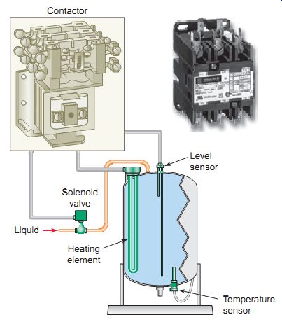
Ill. 3 Contactor used in conjunction with pilot devices. Contactor; Solenoid
valve; Heating element; Temperature sensor; Level sensor; Liquid
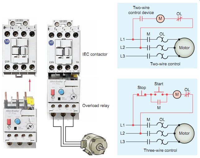
Ill. 4 IEC contactor used in combination with an overload relay module
to switch a motor load. Two-wire control device; Three-wire control
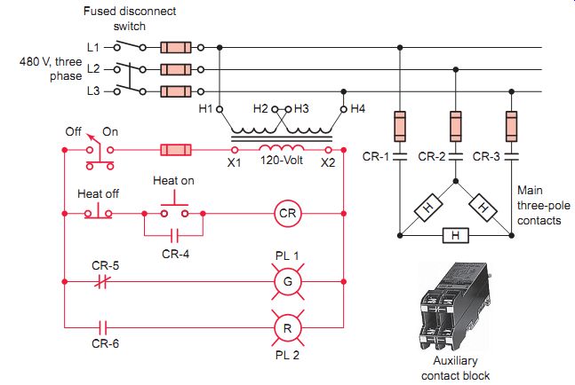
Ill. 5 Heater circuit controlled by a magnetic contactor. Auxiliary contact
block; Main three-pole contacts; Fused disconnect switch
The auxiliary contacts of a contactor have a much lower current rating than the main contacts and are used in control circuits for interlocking, holding, and status indication.
Ill. 5 shows the schematic circuit for a three-phase heater circuit controlled by a three-pole magnetic contactor and operated by a three-wire control circuit. The operation of the circuit can be summarized as follows:
- • A control transformer is used to lower the 480-V line voltage to 120 V for control purposes.
- • The three-wire control circuit's used to switch power to the heating elements.
- • With the on/off switch closed, the heat on push but ton is depressed to energize coil CR of the contactor.
- • Main power contacts CR-1, CR-2, and CR-3 close, energizing the heating elements at line voltage.
- • Auxiliary contact CR-4 closes to hold in the contactor coil by completing a circuit around the heat on push button.
- • At the same time, auxiliary contact CR-5 opens to switch off the green (off) pilot light and contact CR-6 closes to switch on the red (on) pilot light.
- • Depressing the heat off push button or opening the on/off switch will deenergize the coil, returning the circuit to its off state.
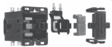
Definite-purpose contactors are specifically designed for applications such as air conditioning, refrigeration, resistive heating, data processing, and lighting. Lighting contactors provide effective control in applications such as office buildings, industrial plants, hospitals, stadiums, and airports. They can be used to handle the switching of tungsten (incandescent filament) or ballast (fluorescent and mercury arc) lamp loads, as well as other general non-motor loads. Contactors may be electrically held or mechanically held. With an electrically held contactor the coil needs to be energized continuously all the time the main contacts are closed. Mechanically held contactors require only a pulse of coil current to change state. Once changed, a mechanical latch holds the main contacts in place so the control power can be removed, resulting in the contactor operation that's quieter, cooler, and more efficient. Ill. 6 shows examples of mechanically and electrically held lighting contactors mounted in enclosures.
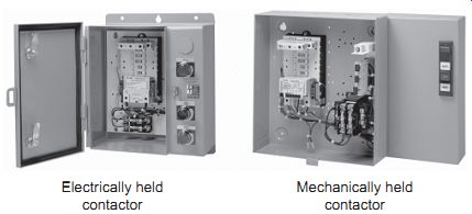
Ill. 6 Electrically and mechanically held lighting contactors. Electrically
held contactor; Mechanically held contactor
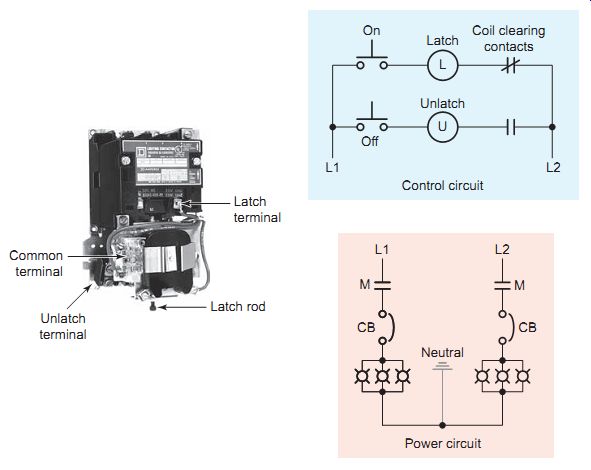
Ill. 7 Mechanically held lighting contactor. Latch terminal Unlatch terminal
Common terminal Latch rod ; Latch Coil clearing contacts; Control circuit;
Power circuit
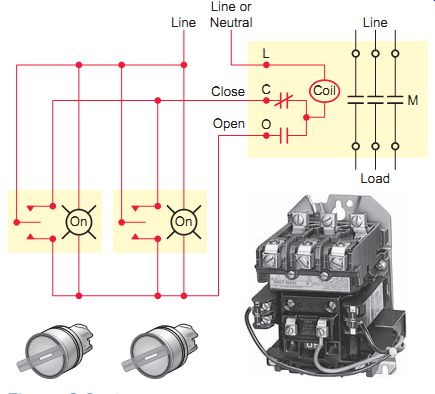
Ill. 8 Single-operating-coil mechanically held lighting contactor.
Ill. 7 shows a typical dual-coil mechanically held lighting contactor and associated circuit. Lighting circuits are single-phase and generally rated at 120 or 277 V. The operation of the circuit can be summarized as follows:
- • When the on button is momentarily depressed, the latch coil is energized through the N.C. clearing contact.
- • As a result, the contactor closes and latches mechanically to close the main contacts (M), lighting the bank of lamps, provided that the circuit breaker is closed.
- • The coil clearing contacts change state (N.C. to N.O. and vice versa) alternately with a change in contactor latching position.
- • To unlatch the contactor, thereby turning the lamps off, the off button is momentarily depressed, unlatching the contactor to open contacts M.
- • Since the latch and unlatch coils are not designed for continuous duty, they are automatically disconnected by the coil clearing contacts to prevent accidental coil burnout should the push button remain closed.
Ill. 8 shows a typical wiring diagram for a mechanically held lighting contactor with a single operating coil that's momentarily energized to either close or open the contactor. In this application the lighting contactor is being controlled from two remotely located (three-position, momentary, center off) control stations. Each control station is equipped with a signal lamp, which indicates the open or closed status of the lighting contactors' main contacts. A wide variety of automatic control devices such as programmable logic controllers (PLCs) and energy management systems can interface with the contactor as well.
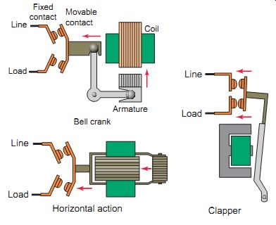
Ill. 9 Typical operating mechanisms for magnetic contactors. Bell crank;
Line Load Armature Coil Movable contact; Fixed contact; Clapper Line Load;
Horizontal action; Load Line
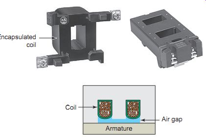
Ill. 10 Contactor coil. Encapsulated coil; Air gap; Armature; Coil; Contactor
Assemblies
Ill. 9 illustrates three typical operating mechanisms for magnetic contactors: bell-crank, horizontal-action, and clapper. Contactor operating mechanisms should be inspected periodically for proper functioning and freedom from sticking or binding. The magnetic circuit of the operating mechanism consists of soft steel with high permeability and low residual magnetism. The magnetic pull developed by the coil must be sufficient to close the armature against the forces of gravity and the contact spring.
The contactor coil is molded into an epoxy resin to increase moisture resistance and coil life. Its shape varies as a function of the type of contactor. A permanent air gap between the magnetic circuit in the closed state prevents the armature from being held in by residual magnetism.
If a coil exhibits evidence of overheating (cracked, melted, or burned insulation), it must be replaced. To mea sure the coil resistance, disconnect one of the coil leads and measure the resistance by setting the ohmmeter to its lowest resistance scale. A defective coil will read zero or infinity, indicating a short or opened coil, respectively.
Contactor coils have a number of insulated turns of wire designed to give the necessary ampere-turns to operate on small currents. As contactors are used to control different line voltages, the voltage used to control the coil may vary. Therefore, when selecting coils you must choose one that matches the available control voltage.
The operational limit of the contactor is between 85 and 110 % of the rated coil voltage. A coil voltage variation of ±5 % will minimize the contact wear. The reason for this is that higher voltages will increase the speed of the electromagnet at closing. Lower voltages will decrease the speed at closing. Both these factors can lead to a higher level of contact bounce at closing, which can be a major cause of wear and erosion.
Magnetic coil voltage specifications include rated volt age, pickup voltage, hold-in voltage, and dropout voltage.
Rated voltage refers to the coil supply voltage and must match that of the control circuit power source. Pickup voltage is the amount of voltage required to overcome the mechanical forces, like gravity and spring tension, trying to keep the contacts from closing. Hold-in voltage is the amount of voltage needed to maintain the contacts in their closed position after pickup voltage is reached (hold-in voltage is normally less than pickup voltage). All contactors that are electrically held in are sensitive to voltage dips occurring in the electrical supply. The dropout volt age is the amount of voltage below which the magnetic field becomes too weak to maintain the contacts in their closed position.
AC and DC contactor coils with the same voltage ratings are not normally interchangeable, the reason being that with a DC coil only the wire ohmic resistance limits the current flow, whereas with AC coils both resistance and reactance (impedance) limit the current flow. Direct cur rent contactor coils have a large number of turns and a high ohmic resistance compared to their AC counterparts.
For a DC-operated coil, since current is limited by resistance only, the current flow through the coil upon closing is the same as the normal energized current flow. However, this isn't the case when the coil is AC operated. With a deenergized AC coil, part of the magnetic path has an air gap because the armature isn't pulled in (Ill. 11). When the contactor closes, the armature closes the magnetic path, causing the inductive reactance of the coil to increase and the current to decrease. This results in a high current to close the contactor and low current to hold it. The inrush current for an AC coil may range from 5 to 20 times that of the sealed current.
When current in an inductive load, such as a contactor coil, is turned off, a very high voltage spike is generated. If not suppressed, these voltage spikes can reach several thou sand volts and produce surges of damaging currents. This is especially true for applications requiring interface with solid-state components such as PLC modules. Ill. 12 shows an RC suppression module wired in parallel (directly across) a contactor coil. The resistor and capacitor connected in series slows the rate of rise of the transient voltage.
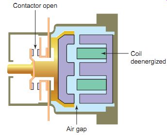
Ill. 11 Deenergized coil air gap. Contactor open; Air gap; Coil deenergized
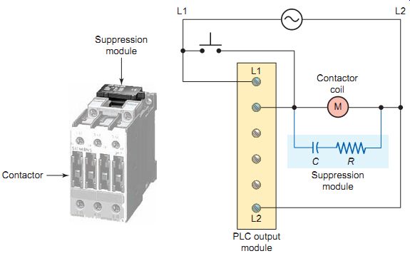
Ill. 12 RC suppression module. Suppression module; Contactor; Contactor
coil; Suppression module
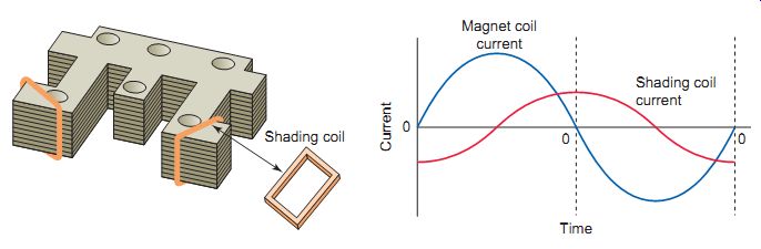
Ill. 13 Shading coil. Magnet coil current; Shading coil current
Contactor coils operated from an AC power source experience changes in the magnetic field surrounding them. The attraction of an electromagnet operating on alternating current is pulsating and equals zero twice during each cycle. As the current goes through zero, the magnetic force decreases and tends to drop the armature out.
When magnetism and force build up again, the armature is pulled back in. This motion of the armature, in and out, makes the contactor buzz or chatter, creating a humming noise and wear on the contactor's moving parts.
The noise and wear of AC contactor assemblies can be prevented by the use of shading coils or rings, as illustrated in Ill. 13. Unlike the contactor coil, shading coils are not electrically connected to the power source, but mounted to inductively couple with the contactor coil.
The shading coil consists of a single turn of conducting material (generally copper or aluminum) mounted on the face of the magnetic assembly. It sets up an auxiliary magnetic attraction that's out of phase with the main field and of sufficient strength to hold the armature tight to the core even though the main magnetic field has reached zero on the sine wave. With well-designed shading coils, AC contactors can be made to operate very quietly. A broken or open shading coil will make its presence known; the contactor will immediately become extremely noisy.
The core and armature of an AC contactor assembly are made of laminated steel, whereas DC assemblies are solid. This is due to the fact that there are no eddy currents generated with continuous direct current applied. Eddy currents are small amounts of current flow induced in the core and armature material by the varying magnetic field produced by AC current flow through the contactor coil.
Using a solid iron core would result in greater circulating currents and for this reason the core of AC coils is made up of a stack of thin insulated laminations.
Misalignment or obstruction of the armature's ability to properly seat when energized causes increased current flow in an AC coil. This could occur as a result of pivot wear or binding, corrosion, or dirt buildup, or pole face damage from impact over a long period of time. Depending on the amount of increased current, the coil may merely run hot, or it may burn out if the current increase is large enough and remains for a sufficient length of time. Improper alignment will create a slight hum coming from the contactor in the closed position. A louder hum will occur if the shading coil is broken because the electromagnet will cause the contactor to chatter.
Today, most contactor contacts are made of a low resistance silver alloy (Ill. 15). Silver contacts are used because they ensure a lower contact resistance than other less expensive materials. Depending on the size of the contactor, the main power contacts can be rated to control several hundred amperes. Most often silver inserts are brazed or welded on copper contacts (on the heel), so silver carries the current and copper carries the arc on interruption. Most manufacturers recommend that silver contacts never be filed. Silver contacts need not be cleaned because the black discoloration that appears is silver oxide, which is a relatively good conductor of electricity.
Contacts are subject to both electrical and mechanical wear as they establish and interrupt electric currents. In most cases mechanical wear is minimal compared to electrical wear. Arcing when the contacts are establishing and interrupting currents causes electrical wear or erosion. Also, contacts will overheat if they transmit too much current, if they don’t close quickly and firmly, or if they open too frequently.
Any of these situations will cause significant deterioration of the contact surface and erratic operation of the contactor.
Ill. 14 Contactor assembly alignment.
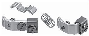
Ill. 15 Typical contactor replacement kit.
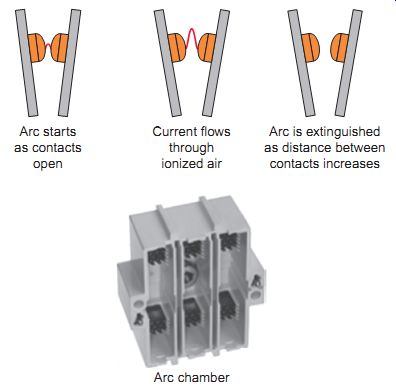
Ill. 16 Electric arc occurs when contacts are opened under load. Arc
chamber; Arc starts as contacts open; Current flows through ionized air;
Arc is extinguished as distance between contacts increases
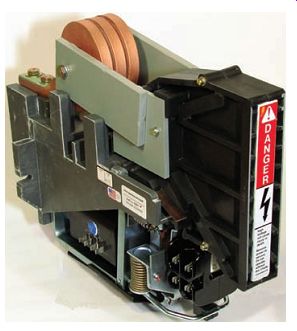
Ill. 17 DC contactor.
Arc Suppression
One of the main reasons contacts wear is the electric arc that occurs when contacts are opened under load. As the contacts open there will still be current flow between the contact surfaces if the voltage across the two points is high enough (Ill. 16). The path for this continued flow is through the ionized air that creates the arc. As the distance between contacts increases, the resistance of the arc increases, the current decreases, and the voltage necessary to sustain the arc across the contacts increases.
Finally, a distance is reached at which full line voltage across the contacts is insufficient to maintain the arc. Arc current can create a substantial temperature rise on the surface of the contacts. This temperature rise may be high enough to cause the contact surfaces to become molten and emit vaporized metal into the gap between the contacts. Therefore, the sooner the arc is extinguished, the better; if allowed to continue, the hot arc will melt the contact surface. Most contactors contain some type of arc chamber to help extinguish the arc.
Factors that contribute significantly to contact arcing include:
• The level of voltage and current being switched.
As circuit voltage and current increase, the gap between the opening contacts ionizes more rapidly into a conductive path.
• Whether the voltage being switched is AC or DC. Direct current arcs are considerably more difficult to extinguish than AC arcs. An AC arc is self-extinguishing; the arc will normally extinguish as the AC cycle passes through zero. In the case of a DC supply there is no current zero, as the current is always in one direction, so no natural arc extinction properties exist.
• The type of load (resistive versus inductive). With resistive loads the duration of the arc is primarily determined by the speed at which the contacts separate. With inductive loads the release of stored energy built up in the magnetic field serves to maintain the current and cause voltage spikes. Inductive loads in AC circuits are less of a problem than in DC circuits.
• How quickly the contactor operates. The faster the speed of contact separation, the quicker the arc will be extinguished.
Arcing may also occur on contactors when they are closing, E.g. , if the contacts come close enough together that a voltage breakdown occurs and the arc is able to bridge the open space between the contacts.
Another way this can occur is if a rough edge of one con tact touches the other first and melts, causing an ionized path that allows current to flow. In either case, the arc lasts until the contact surfaces are fully closed.
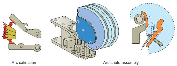
Ill. 18 Arc chute. Arc extinction Arc chute assembly
One major difference between AC and DC contactors is the electrical and mechanical requirements necessary for suppressing the arcs created in opening and closing contacts under load. To combat prolonged arcing in DC circuits, the contactor switching mechanism is constructed so that the contacts will separate rapidly and with enough air gap to extinguish the arc as soon as possible on opening. DC contactors are larger than equivalently rated AC types to allow for the additional air gap. It’s also necessary in closing DC contacts to move the contacts together as quickly as possible to avoid some of the same problems encountered in opening them. For this reason, the operating speeds of DC contactors are designed to be faster than those of AC contactors.
An arc chute or shield is a device designed to help confine, divide, and cool an arc, so that the arc is less likely to sustain itself. There is one arc chute for each set of contacts that's fitted above the moving and fixed contact. Arc chutes split the arc established at contactor tips while breaking the current to quench the arc. In addition, they also provide barriers between line voltages.
The arc chutes used in AC contactors are similar in construction to those used in DC contactors. However, in addition to arc chutes, most DC contactors employ magnetic blowout coils to assist with arc suppression. Blow out coils consist of heavy copper coils mounted above the contacts and connected in series with them. Current flow through the blowout coil sets up a magnetic field between the breaking contacts that "blows" out the arc. When an arc is formed, the arc sets up a magnetic field around itself. The magnetic field of the arc and the blowout coil repel each other. The net result is an upward push that makes the arc become longer and longer until it breaks and is extinguished.
Blowout coils seldom wear out or give trouble when operated within their voltage and current ratings. Arc chutes are constantly subjected to the intense heat of arcing and may eventually burn away, allowing the arc to short-circuit to the metal blowout pole pieces. Therefore, arc chutes should be inspected regularly and replaced before they burn through.
As part of a preventive maintenance program, large contactors should be checked periodically for contact wear, contact wipe, shunt terminal connections, free movement of the armature, blowout structure, blowout coil connections, coil structure, correct contact spring tension, and correct air gap. Normally the slight rubbing action and burning that occur during normal operation keep the contact surfaces clean for proper operation. Copper contacts, still used on some contactors, should be cleaned to reduce contact resistance. Worn contacts should always be replaced in pairs to ensure that complete and proper surface contact is maintained. High contact resistance produces overheating of contacts as well as a significant voltage drop across the contacts, resulting in less voltage being delivered to the load.
A vacuum contactor switches power contacts inside a sealed vacuum bottle. The vacuum provides a better environment than free air for breaking the arc because without air to ionize, the arc extinguishes more quickly. Housed in vacuum bottles, the arc is isolated and the contacts are protected from dust and corrosion. Com pared to conventional air contactors they offer a significantly higher electrical endurance and are the preferred switching devices in applications with a high switching frequency, for heavy-duty starting, and for line voltages above 600 V.
QUIZ:
1. What’s the NEMA definition for a magnetic contactor?
2. Two circuits are involved in the operation of a magnetic contactor. Identify these circuits and the part of the contactor each connects to.
3. Give a brief description of how a magnetic contactor operates.
4. A micro switch, when activated, is used to switch current to a solenoid valve coil by way of a magnetic contactor. To which circuits of the contactor would each device be wired?
5. A magnetic contactor that has a coil rated for 24V AC is fed from a 240-V AC power supply.
What would most likely be used to lower the voltage level for the coil?
6. Compare the operation of electrically and mechanically held magnetic contactors.
7. List three types of operating mechanisms for magnetic contactors.
8. Why is the contactor coil molded into an epoxy resin?
9. What’s the negative effect of operating a contactor coil above or below its rated voltage?
10. Which contactor coil rating refers to the amount of voltage below which the magnetic field becomes too weak to maintain the contacts in their closed position?
11. Explain why the inrush current to an AC contactor coil is much higher than its normal operating current.
12. Explain how a shading coil prevents an AC contactor from chattering.
13. Why are AC contactor assemblies made of laminated steel?
14. In what way can misalignment of the armature and core of an AC contactor cause a contactor coil to run hot?
15. Why do manufacturers recommend that discolored silver contacts not be filed?
16. Why do contactors require some form of arc suppression?
17. Does the severity of contact arcing increase or decrease with each of the following changes?
a. A decrease in the voltage level
b. Use of an AC rather than a DC power source
c. Change of load from resistive type to inductive type
d. An increase in the speed of contact separation
18. Why is it harder to extinguish an arc on contacts passing direct current than on contacts passing alternating current?
19. Compare the design features of AC and DC contactors.
20. What’s the function of an arc chute?
21. Explain the operation of the blowout coil used in DC contactors.
22. List six things to check as part of routine preventive maintenance for large contactors.
23. a. Explain the main advantage of using a vacuum contactor.
b. List three common switching applications for vacuum contactors.
Cont. to part 2