AMAZON multi-meters discounts AMAZON oscilloscope discounts
Cont. from part 6
Motor Installation
Knowledge of proper installation techniques is vital to the effective operation of a motor. The following are some of the important motor installation procedures that need to be considered.
Foundation
A rigid foundation is essential for minimum vibration and proper alignment between motor and load. Concrete makes the best foundation, particularly for large motors and driven loads.
Mounting
Unless specified otherwise, motors can be mounted in any position or any angle. Mount motors securely to the mounting base of equipment or to a rigid, flat surface, preferably metallic. An adjustable motor base makes the installation, tensioning, and replacements of belts easier.
Common types of motor mountings are shown and include:
Rigid base, which is bolted, welded, or cast on the mainframe and allows the motor to be rigidly mounted on equipment.
Resilient base, which has isolation or resilient rings between motor mounting hubs and base to absorb vibration and noise. A conductor is imbedded in the ring to complete the circuit for grounding purposes.
NEMA C face mount, which has a machined face with a pilot on the shaft end that allows direct mounting with a pump or other direct-coupled equipment.
Bolts pass through mounted part to threaded hole in the motor face.
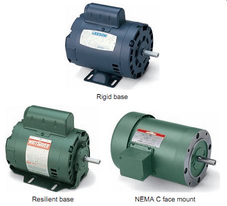
Ill. 65 Common types of motor mountings. Leeson, www.leeson.com. Rigid
base; Resilient base; NEMA C face mount
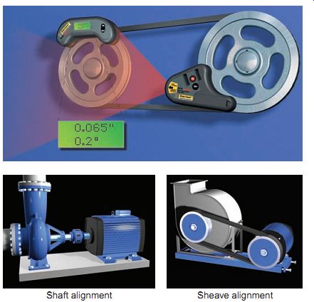
Ill. 66 Laser alignment kit. Shaft alignment Sheave alignment
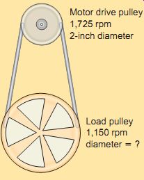
Ill. 67 Motor drive pulley 1,725 rpm 2” diameter Load pulley 1,150 rpm
diameter
EXAMPLE:
Problem: You have a motor to drive a load. The motor operates at 1,725 rpm and has a pulley with a 2-inch diameter; the load must operate at 1,150 rpm. What size of pulley is needed for the load?
Solution: Motor rpm/Equipment rpm = Equipment pulley diameter/ Motor pulley diameter
1,725/ 1,150 = Equipment pulley diameter/ 2
1,725 × 2/ 1,150 = 3-inch pulley
Motor and Load Alignment
Misalignment between the motor shaft and the load shaft causes unnecessary vibration and failure due to mechanical problems. Premature bearing failure in the motor and/or the load can result from misalignment. Different types of alignment devices, such as the laser alignment kit, are used for motor and load alignment. Positioning a motor or placing a shim (thin piece of metal) under the feet of the motor is often part of the alignment process.
Direct-drive motors, as the name implies, supply torque and speed to the load directly. A motor coupling is used to mechanically connect axially located motor shafts with equipment shafts. Direct coupling of the motor shaft to the driven load results in a 1:1 speed ratio. For direct-coupled motors, the motor shaft must be centered with the load shaft to optimize operating efficiency. A flexible coupling permits the motor to operate the driven load while allowing for slight misalignments.
Coupling by means of gears or pulleys/belts may be used in cases where the application requires other than standard available speed. Variable speeds are possible by making available several gear ratios or pulleys with variable diameters. Matching a motor to a load involves transformation of power between shafts, often from a high-speed/low torque drive shaft to a low-speed/high-torque load shaft.
Multiple belts are often used together in order to increase carrying power. If the pulley wheels are different sizes, the smaller one will spin faster than the larger one. Changing pulley ratios does not change horsepower, only torque and speed. The following formula can be used to calculate speed and pulley sizes for belt-drive systems.
Motor rpm / Equipment rpm = Equipment pulley diameter / Motor pulley diameter
Y-belts are common belts used for power transmission.
They have a flat bottom and tapered sides and transmit motion between two sheaves. When servicing a belt-drive system, the belts must be checked for proper tension and alignment. The belt should be tight enough not to slip, but not so tight as to over load motor bearings. Belt deflection should be 1/64 inch per inch of span. A belt tension gauge is used to ensure proper specified belt tension. Misalignment is one of the most common causes of premature belt failure. Angular misalignment is misalignment caused by two shafts that are not parallel. Parallel misalignment is caused by two shafts that are parallel but not on the same axis.
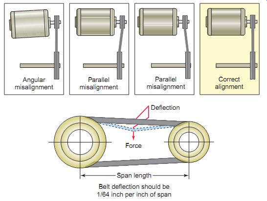
Ill. 68 Servicing a belt-drive system. Span length Deflection; Force;
Belt deflection should be 1/64 inch per inch of span; Angular misalignment;
Parallel misalignment; Parallel misalignment; Correct alignment
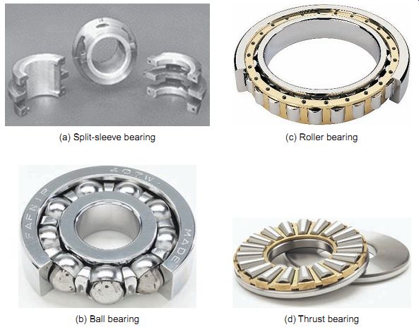
Ill. 69 Motor bearings. Canadian Babbitt Bearings, www.cbb.ca. The Timken
Company. (a) Split-sleeve bearing (b) Ball bearing (c) Roller bearing
(d) Thrust bearing
Motor Bearings
The rotating shaft of a motor is suspended in the end bells by bearings that provide a relatively rigid support for the output shaft. Motors come equipped with different types of bearings properly lubricated to prevent metal-to-metal contact of the motor shaft (Ill. 69). The lubricant used is usually either grease or oil. Most motors built today have sealed-bearing lubrication. This should be checked periodically to ensure the sealing has not been compromised and the bearing lubricant lost. For installations using older motors that require regular lubrication, this should be done on a scheduled basis, in conformance with the manufacturer's recommendations.
Sleeve bearings used on smaller light-duty motors consist of a bronze or brass cylinder, a wick, and a reservoir. The shaft of the motor rotates in the bronze or brass sleeve and is lubricated with oil from the reservoir by the wick, which transfers oil from the reservoir to the sleeve. Large motors (200 hp and over) are often equipped with large split-sleeve bearings that mount on the top and bottom half of the motor end shield. These bearings are usually poured with a material called babbitt and then bored to size. Sleeve bearings are furnished with oil reservoirs, sight gauges, level gauges, and drain provisions.
Ball bearings are the most common type of bearing.
They carry heavier loads and can withstand severe applications. In a ball bearing, the load is transmitted from the outer race to the ball, and from the ball to the inner race. Ball bearings come in three different styles: permanently lubricated, hand packed, and bearings that require lubrication through fitting. Not lubricating the bearings can damage a motor for obvious reasons; too much grease can overpack bearings and cause them to run hot, shortening their life. Excessive lubricant can find its way inside the motor where it collects dirt and causes insulation deterioration and overheating.
Roller bearings are used in large motors for belted loads. In these bearings, the roller is a cylinder, so this spreads the load out over a larger area, allowing the bearing to handle much greater loads than a ball bearing.
Thrust bearings consist of two thrust races and a set of rollers that are designed to handle higher than normal axial forces exerted on the shaft of the motors, as is the case with some fan and pump blade applications. Motors for vertically mounted motors typically use thrust bearings.
Electrical Connections
NEMA standards and Article 430 of the NEC, as well as state and local codes, provide specific electrical and mechanical installation requirements and recommendations covering motors and motor controls. The motor must be connected to a power source corresponding to the volt age and frequency rating shown on the motor nameplate.
After you've verified that the supply voltage requirements are correct, you then can make the motor terminal connections. Stator winding connections should be made as shown on the nameplate connection diagram or in accordance with the wiring diagram attached to the inside of the conduit box cover.
Grounding
Both your motor and the equipment or apparatus to which it’s connected must be grounded as a precaution against the hazards of electrical shock and electrostatic discharge.
This is done by using an equipment-grounding conductor that establishes a path or circuit for ground-fault current to facilitate overcurrent device operation. The equipment grounding conductor may be a conductor (insulated or bare) run with the circuit conductors, or where metal raceways are used, the raceway may be the equipment- grounding conductor. The color green is reserved for an insulated grounding conductor. In addition to helping prevent electrical shock, grounding of an electronic motor drive also helps to reduce unwanted electrical noise that can interfere with the proper operation of the electronic motor drive circuits.
Electrical currents are induced onto the motor's rotor shaft and seek the least resistant path to ground-usually the motor bearings. Shaft voltages accumulate on the rotor until they exceed the dielectric capacity of the motor bearing lubricant; then the voltage discharges in a short pulse to ground through the bearing. The random and frequent discharging has an electric discharge machining (EDM) effect, causing pitting of the bearing's rolling elements and raceways that eventually can lead to bearing failure. This occurs more often in AC motors controlled by variable-frequency drives. For this reason proper grounding is especially critical on the motor frame, between the motor and drive, and from the drive to earth. Grounding the motor shaft by installing a grounding device, prevents bearing damage by dissipating shaft currents to ground.
===
EXAMPLE
Problem: What size THW CU conductors are required for a single 15-hp, three-phase, 230-V squirrel cage motor?
Solution: Step 1 Determine the full-load current (FLC) rating of the motor to be used in determining the conductor size.
NEC 430.6 requires that tables 430.247 through 430.250 be used to determine the FLC and not the nameplate rating. Table 430.250 deals with three-phase alternating cur rent motors, and using this table, we find that for a 10-hp, 208-V, three-phase motor the FLC is 42 amperes.
Step 2 NEC 430.22 requires branch circuit conductors supplying a single motor to have an ampacity not less than 125 % of the motor FLC. Therefore, Rated ampacity = 42A × 125% = 52.5A
Step 3 According to Table 310.16, the conductor size required would be:
6 AWG THW CU
---
Problem: What is the % voltage unbalance for a three-phase supply voltage of 480 V, 435 V, and 455 V?
Solution: Average voltage deviation = 480 + 435 + 445 /3 = 1,360/3 = 453 V
===
Conductor Size
The size of the motor branch circuit conductors is deter mined in accordance with Article 430 of the NEC, based on the motor full-load current, and increased where required to limit voltage drop. Undersized wire between the motor and power source will limit stating abilities and cause overheating of the motor.
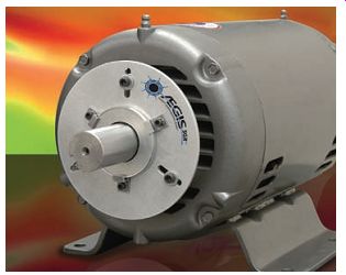
Ill. 70 Motor shaft grounding ring. Electro Static Technology-an ITW
Co., www.est-aegis.com.
Voltage Levels and Balance
Motor voltages should be kept as close to the nameplate value as possible, with a maximum deviation of 5 %.
Although motors are designed to operate within 10 per cent of nameplate voltage, large voltage variations can have negative effects on torque, slip, current, efficiency, power factor, temperature, and service life.
Unbalanced motor voltages applied to a polyphase induction motor may cause unbalanced currents, resulting in overheating of the motor's stator windings and rotor bars, shorter insulation life, and wasted energy in the form of heat. When three-phase line voltages are not equal in magnitude, they are said to be unbalanced. A voltage unbalance can magnify the % current unbalance in the stator windings of a motor by as much as 6 to 10 times the percent voltage unbalance. Acceptable volt age unbalance is typically not more than 1 %. When there is a 2 % or greater voltage unbalance, steps must be taken to determine and rectify the source of the unbalance. In cases where the voltage unbalance exceeds 5 %, it’s not advisable to operate the motor at all.
The voltage unbalance is calculated as follows:
Percent voltage unbalance = Maximum voltage deviation from the voltage average / Average voltage × 100
Maximum deviation from the average voltage = 480 - 453 = 27V.
Percent voltage unbalance = Maximum voltage deviation from the voltage average/Average voltage × 100 = 27 /453 × 100 = 5.96%
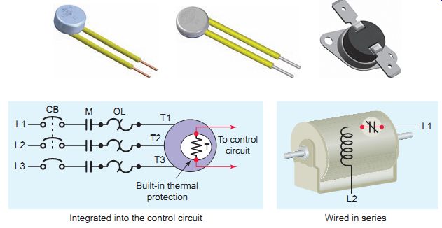
Ill. 72 Built-in thermal motor protection. Wired in series Integrated
into the control circuit.
Built-in Thermal Protection
Overload relays mounted on the motor starter enclosure protect the motor by monitoring the motor current and resultant heat it creates inside the motor. They do not, however, monitor the actual amount of heat generated within the winding. Motors subject to such conditions as excessive starting cycles, high ambient motor temperatures, or inadequate ventilation conditions may experience rapid heat buildup that is not sensed by the overload relay. To minimize such risks, the use of motors with thermal protectors inside that sense motor winding temperature is advisable for most applications. These devices may be integrated into the control circuit to offer additional overload protection to the motor or connected in series with the motor windings on smaller single-phase motors. Basic types include:
Automatic reset: After the motor cools, this line interrupting protector automatically restores power. It should not be used where unexpected restarting would be hazardous.
Manual reset: This line-interrupting protector has an external button that must be pushed to restore power to the motor. Use where unexpected restarting would be hazardous, as on saws, conveyors, compressors, and other machinery.
Resistance temperature detectors: Precision calibrated resistors are mounted in the motor and are used in conjunction with an instrument to detect high temperatures.
QUIZ:
1. List three popular types of motor mountings.
2. A motor with a 3-inch drive pulley operating at a speed of 3,600 rpm is belt-coupled to an equipment pulley 8 inches in diameter. Calculate the speed of the driven load.
3. List four basic types of bearing and give a typical application for each.
4. How can a motor be damaged by over-lubricating a ball bearing?
5. Which NEC article deals specifically with requirements for electric motors?
6. Why is it desirable to ground the motor shaft in addition to the frame?
7. In what ways can undersized wiring between the motor and power source affect the operation of a motor?
8. What negative effects can unbalanced three phase line voltages have on the operation of a motor?
9. In what type of application is it advisable to use manual-reset built-in thermal protectors?
Electric Motors + Motor-Control Systems
(Nested-content Series)
Electric Motors
Motor Maintenance and Troubleshooting
Motor Maintenance
In general, motors are very reliable machines that require little maintenance. But while a typical electric motor might be a low-maintenance item, it still requires regular maintenance if it’s to achieve the longest possible service life.
SCHEDULE PERIODIC INSPECTIONS
The key to minimizing motor problems is scheduled routine inspection and service. Keep records of all maintenance schedules and procedures performed. The frequency and procedures of routine service vary widely between applications. Motors should be inspected periodically for things such as shaft alignment, motor base tightness, and belt condition and tension.
BRUSH and COMMUTATOR CARE
For DC motors, remove the covers and perform checks on brush wear, spring tension, and commutator wear or scoring. Replace the brushes if there is any chance they won’t last until the next inspection date. The commutator should be clean, smooth, and have a polished brown surface where the brushes ride. Observe the brushes while the motor is running. The brushes must ride on the commutator smoothly with little or no sparking and no brush chatter.
TESTING WINDING INSULATION
Twice yearly, test winding and winding-to-ground resistance to identify insulation problems. Motors that have been flooded or have low megger readings should be thoroughly cleaned and dried before being energized. The following are typical minimum motor insulation resistance values:
Rated Motor; Voltage; Minimum; Insulation; Resistance;
600 V and below 1.5 M-ohm 2,300 V 3.5 M-ohm
4000 V 5.0 M-ohm
KEEP YOUR MOTORS CLEAN
Wipe, brush, vacuum, or blow accumulated dirt from the frame and air passages of the motor. Dirty motors run hot when thick dirt insulates the frame and clogged passages reduce cooling airflow. Heat reduces insulation life and eventually causes motor failure.
KEEP YOUR MOTORS DRY
Motors that are used continuously are not prone to moisture problems. It’s the intermittent use or standby motor that may have difficulties. Try to run the motor for at least a few hours each week to drive off moisture. Be careful that steam and water are not directed into open drip-proof motors.
CHECK LUBRICATION
Lubricate motors according to manufacturer specifications. Apply high-quality greases or oils carefully to pre vent contamination by dirt or water.
CHECK FOR EXCESSIVE HEAT, NOISE, and VIBRATION
Feel the motor frame and bearings for excessive heat or vibration. Listen for abnormal noise. All indicate a possible system failure. Promptly identify and eliminate the source of the heat, noise, or vibration.
EXCESSIVE STARTING IS A PRIME CAUSE OF MOTOR FAILURES
The high current flow during start-up contributes a great amount of heat to the motor. For motors 200 hp and below, the maximum acceleration time a motor connected to a high-inertia load can tolerate is about 20 seconds.
The motor should not exceed more than about 150 "start seconds" per day.
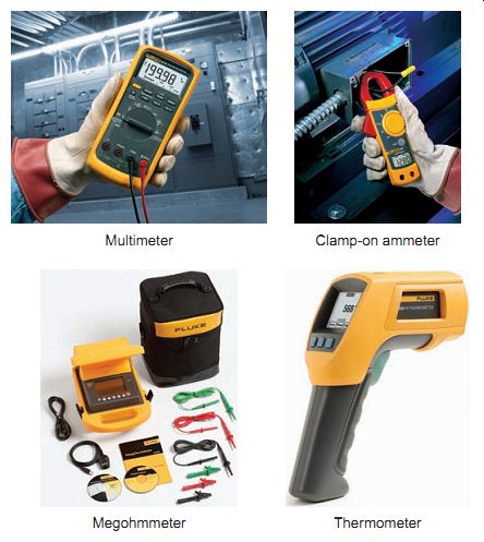
Ill. 73 Instruments used for motor troubleshooting. www.fluke.com. Megohmmeter
Thermometer. Multimeter Clamp-on ammeter.
Troubleshooting Motors
Electric motor failures can be due to mechanical component failure or electrical circuit failure. Any type of electrical testing involves risk, and complacency can lead to injury! When working on any type of motor, to reduce the risk of injury be certain to:
• Disconnect power to the motor and complete lock out and tag-out procedures before performing ser vice or maintenance.
• Discharge all capacitors before servicing the motor.
• Always keep hands and clothing away from moving parts.
• Be sure required safety guards are in place before starting equipment.
Electrical contact accounts for one-fifth of all construction deaths. Never work on energized equipment unless this is absolutely necessary for examination, adjustment, servicing, or maintenance. When you find you must work on energized equipment, always wear the appropriate personal protective equipment and use appropriate tools and equipment. Use the "buddy rule" and never work on energized equipment alone. Always have a partner working with you, in case of emergency.
Typical instruments used for troubleshooting motor operation problems include a multimeter, clamp-on ammeter, megohmmeter, and infrared thermometer. These instruments, are used to measure voltage, current, resistance, insulation resistance, and temperature.
The basic motor system consists of the power supply, controller, motor, and driven load. When a motor problem occurs, it’s first necessary to find which of the parts of the system is at fault. Power supplies and controllers can fail as well as the motor itself. Mechanical loads can increase because of an increased size of the load the motor is driving, or failure of bearings or coupling mechanisms.
Mechanical overloading is a prime cause of motor failure.
TROUBLESHOOTING GUIDES
Once it has determined that the motor is at fault, you can proceed to locate the problem with the motor. A troubleshooting guide outlines a comprehensive variety of motor problems.
Generally the categories are arranged according to symptoms, offering brief suggestions concerning what to look for when investigating motor failures and often providing advice on how to correct the problem once it has been identified.
The following is an example of a troubleshooting guide that outlines fault symptoms common to most types of motors.
1. Symptom: The motor fails to start. Possible causes:
- Blown fuse or open circuit breaker. Check the volt age at the input and output of the overcurrent protection device. If voltage is measured at the input but not at the output, the fuse is blown or the circuit breaker is open.
- Check the rating of the fuse or circuit breaker. It should be at least 125 % of the motor's full-load current.
- Motor overload relay on starter tripped. Allow overload relay to cool and reset it. If the motor causes the overload relay to open after a short period, check for motor short circuits and grounds. Check the full load current of the motor and compare it to the setting of the overload relay.
- Low voltage or no voltage applied to the motor.
- Check the voltage at the motor terminals. The volt age must be within 10 % of the motor nameplate voltage. Determine the cause of the low voltage.
- Loose fuse clips and connections at the terminals of the disconnect switch or circuit breaker can result in low voltage at the motor.
- Mechanical overload. Rotate the motor shaft to see if a binding load is the problem. Check for frozen bearings.
- Check the air gap between the stator and rotor. Reduce the load or try operating the motor with no load applied.
- Defective motor windings. Make resistance checks of the motor windings for opens and shorts in coil windings and coils shorted to ground faults. An ohmmeter reading of infinity across a set of coil windings means that there is an open somewhere-sometimes it’s at one end of the coil and accessible for repair. A short circuit in only a few turns of a coil, while difficult to detect, will still result in a motor overheating. One way to test for a short circuited coil winding is to compare its resistance reading with that of a known good identical coil.
- Burnt-out motor. If one or more of the motor windings looks blackened and smells burnt, it’s most likely burnt out and needs to be replaced.
2. Symptom: The motor overheats. Possible causes:
- Load. A basic rule is that your motor should not get too hot to touch. Check ammeter reading against full load current rating of motor. For a higher-than-normal current reading, reduce the load or replace motor with a larger sized one.
- Insufficient cooling. Remove any buildup of debris in or around the motor.
- Ambient temperature. Higher-than-normal ambient temperatures. Take steps to improve the motor's ventilation and/or lower the ambient temperature.
- Bearings and alignment. Bad bearings or poor coupling alignment can increase friction and heat.
- Source voltage. If the operating voltage is too high or too low, the motor will operate at a higher temperature. Correct voltage to within 10 % of the motor's rating.
3. Symptom: Excessive motor noise and vibration. Possible causes:
- Bearings. With the motor stopped, try gently moving the shaft up and down to detect bearing wear. Use a stethoscope to check the bearings for noise. When the handle of a screwdriver is placed to the ear and the blade to the bearing housing, the screwdriver will amplify the noise, like a stethoscope. Replace worn or loose bearings. Replace dirty or worn-out oil or grease.
- Coupling mechanism. Check for bent shaft on motor or load. Straighten if necessary. Measure the alignment of the couplings. Realign if necessary.
- Loose hardware. Tighten all loose components on the motor and load. Check fasteners on the motor and load mounts. Motors with centrifugal mechanisms, brushes, slip rings, and commutators can cause noise due to wear and looseness of the mechanisms.
4. Symptom: Motor produces an electric shock when touched. Possible cause:
- Grounding. Broken or disconnected equipment grounding conductor. Motor winding short-circuited to frame. Check motor junction box for poor connections, damaged insulation, or leads making electrical connection with the frame.
5. Symptom: Motor overload protector continually trips. Possible cause:
- Load. Load too high. Verify that the load is not jammed. Remove the load from the motor and measure the no-load current. It notably should be less than the full-load rating stamped on the nameplate.
- Ambient temperature too high. Verify that the motor is getting air for proper cooling.
- Overload protector may be defective. Replace the motor's protector with one of the correct rating.
- Winding short-circuited or grounded. Inspect windings for defects and loose or cut wires that may cause a path to ground.
TROUBLESHOOTING Q&A
Troubleshooting Q&A may be used to quickly identify common problems and possible corrective courses of action. The following are examples that pertain to specific motor types.
--------
Single-Phase Motors
Problem:
- Split-phase motor hums, and it will run normally if started by hand.
- Capacitor-start motor hums, and it will run normally if started by hand.
- Start capacitors continuously fail.
- Run capacitor fail.
- Universal motor sparks.
Probable Cause and Course of Action:
- Centrifugal switch is not operating properly. Disassemble the mechanism. Clean the contacts. Adjust spring tension. Replace switch.
- Centrifugal switch (same as for split-phase motor). Defective capacitor. Test capacitor. If defective replace.
- The motor is not coming up to speed quickly enough as a result of not being sized properly.
- The motor is being cycled too frequently. Capacitor manufacturers recommend no more than twenty 3-second starts per hour.
- Starting switch may be defective, preventing the motor from opening the start winding circuit.
- Ambient temperature too high.
- Possible power surge to motor caused by high transient voltage. If a common problem install a surge protector.
- New brushes not properly seated. Seat brushes with fine sandpaper to fit contour of commutator.
- Worn or sticky brushes. Replace brushes or clean brush holder.
- Open- or short-circuited armature coils. Replace armature.
------------
Three-Phase Motors
Problem:
- Single-phasing-one phase of the three phase system is lost. Motor won’t start, but if in operation may continue to operate at increased current and diminished capacity.
- Unique high-pitched sound from motor.
- Unbalanced three-phase voltage-the voltages of all phases of a three-phase power supply are not equal. A voltage imbalance of 3.5% between phases will cause a temperature rise of 25°C in the motor. Motor operates at a higher-than normal temperature and reduced efficiency.
- Wound-rotor induction motor fails to start or starts and runs erratically.
- Synchronous motor experiences increased start-up times or erratic acceleration.
Probable Cause and Course of Action:
- A fuse is blown or one leg of a circuit breaker is open. Check each of the three-phase power lines for correct voltage.
- Blown fuse on power factor correction capacitor bank-find and replace fuse.
- Uneven single-phase loading-distribute single-phase loads more evenly on the three-phase circuit.
- Utility unbalanced voltages-if the incoming voltages are substantially unbalanced, contact the utility and ask them to correct the problem.
- Harmonic distortion-The presence of harmonic distortion in the applied voltage to a motor will increase motor temperature, which could result in insulation damage and possible failure.
- Locate the sources of the harmonics and use harmonic filters to control or reduce harmonics.
- External rotor resistors-Look for failed components in the resistor bank when troubleshooting. Clean slip rings and check brushes for wear and proper pressure.
- Damaged or defective amortisseur windings-Historical inrush testing that records the stator's current during start-up can greatly assist in determining if these windings have degraded over the life of the motor.
------------------
Direct-Current Motors
Problem:
- Excessive arcing at brushes.
- Rapid brush wear.
Probable Cause and Course of Action:
- Worn or sticky brushes. Replace brushes or clean brush holder.
- Incorrect brush position with respect to neutral plane. Rotate brush rigging to the correct position to aid in commutation.
- Overload. Measure current to the motor and compare to full-load current rating. If necessary, reduce motor load.
- Dirty commutator. The commutator surface should be clean and bright; slight scratches and discoloring can be removed with emery paper. Deep scratches/ridges require the commutator to be machined and mica-undercut.
- Armature faults. Test for open- and short-circuited windings in the armature and correct or replace motor.
- Field-winding faults. Test for short circuits, open circuits, and ground faults and correct or replace motor.
- Wrong brush material, type, or grade. Replace with brushes recommended by manufacturer.
- Incorrect brush tension. Adjust brush tension so that the brush rides freely on the commutator. Replace brush springs if tension measured by a scale is insufficient.
---------------
TROUBLESHOOTING DECISION TREE
A troubleshooting ladder or tree may be used to guide you through the steps of the troubleshooting process. A trouble shooting ladder is sequential in nature, and its simplicity can often save time in arriving at the source of a motor problem. The following is a typical example of a trouble shooting ladder used to determine the cause of overheating of a three-phase squirrel-cage induction motor.
Problem--Motor Overheats:
Step 1 Is ambient temperature too high? NO/YES Reduce ambient, increase ventilation or install larger motor.
Step 2 Is motor too small for present operating conditions? NO/YES Install larger motor.
Step 3 Is motor started too frequently? NO/YES Reduce starting cycle or use larger motor.
Step 4 Check external frame. Is it covered with dirt, which acts as insulation and prevents proper cooling? NO/YES Wipe, scrape, or vacuum accumulated dirt from frame.
Step 5 Feel output from air exhaust openings. Is flow light or inconsistent, indicating poor ventilation? NO YES Remove obstructions or dirt preventing free circulation of airflow. If needed, clean internal air passages.
Step 6 Check input current while motor drives load. Is it excessive, indicating an overload? YES NO Go to Step 11
Step 7 Is the driven equipment overloaded? NO YES Reduce load or install larger motor.
Step 8 Are misalignments, bad bearings, or damaged components causing excessive friction in driven machine or power transmission system? NO YES Repair or replace bad components.
Step 9 Are motor bearings dry? YES Lubricate. Does motor still draw excessive current?
Step 10 Are damaged end bells, rubbing fan, bent shaft, or rubbing rotor causing excessive internal friction? NO YES Repair or replace motor.
Step 11 Are bad bearings causing excessive friction? NO YES Determine cause of bad bearings.
Step 12 Check phase voltage. Does it vary between phases? NO YES Restore equal voltage on all phases.
Step 13 Is voltage more than 10% above or 10% below nameplate? NO YES Restore proper voltage or install motor built for the voltage.
Step 14 Check stator. Are any coils grounded or short-circuited? YES Repair coils or replace motor.
QUIZ:
1. From a safety perspective, what is the first step to be taken before performing any type of motor maintenance?
2. Outline five common motor maintenance tasks that should be performed as part of a motor preventive maintenance program.
3. Outline how to test for each of the following suspected motor problems.
a. Blown fuse or open circuit breaker.
b. Low voltage applied to the motor.
c. Defective motor windings.
4. List five possible causes of motor overheating.
5. The centrifugal switch of a spilt-phase motor fails and remains open at all times. How would this affect the operation of the motor?
6. The centrifugal switch of a capacitor start motor fails and remains closed at all times. How would this affect the operation of the motor?
7. List four possible causes of unbalanced voltages on the supply voltage of a three-phase motor circuit.
8. List five possible causes of excessive arcing at the brushes of a DC motor.
TROUBLESHOOTING SITUATIONS and SCENARIOS:
1 . Assume the tags used to identify the six motor leads of a compound-wound DC motor are suspected of being incorrectly marked or missing.
a . Outline how an ohmmeter would be used to identify the armature, shunt field, and series field leads.
b . What operating test could be made to ensure cumulative connection of the shunt and series field?
2. One of the three-phase line fuses to a squirrel-cage induction motor burns open while the motor is operating.
a . Will the motor continue to rotate? Why?
b . In what way might this operating condition damage the motor?
c. Should the motor be able to restart on its own? Why?
3. A defective motor start capacitor rated for 130 µF and 125 V AC is replaced with one rated for 64 µF and 125 V AC. What would happen?
4. The speed of a motor is to be reduced by one-half by using two different size pulleys. What must the relative diameters of the motor drive and load pulley be?
5. A motor feels hot to the touch. Does this always indicate it’s operating at too high a temperature? Explain.
MORE QUESTIONS:
1 . Explain how a squirrel-cage rotor produces a magnetic field.
2. List the different types of motor measurements that are used for troubleshooting motors.
3. Why does a single-phase motor have no starting torque if only a single winding is used?
4. How would you determine the running and starting winding of a single-phase motor from a visual inspection of the stator?
5. Arrange the following single-phase motors in the order of decreasing torque, with the highest torque first: split-phase, universal, shaded pole, capacitor.
6. How does slip affect motor speed?
7. Describe the major physical and electrical differences between the three major three-phase motor types.
8. Can a single-phase motor be operated from a three phase power supply? Explain.
9. Assume you have to purchase a motor and load laser alignment kit. Search the Internet for suppliers and prepare a report on the features and operation of the one you would consider purchasing.
10. An energy-efficient motor produces the same shaft output power (hp), but uses less input power (kW) than a standard-efficiency motor. Visit the website of a motor manufacturer and compare the price and features of a standard-efficiency motor with that of an equivalent energy-efficient motor.
11. Explain why motors are more efficient at full load.
Cont. to part 8