AMAZON multi-meters discounts AMAZON oscilloscope discounts
Cont. from part 3
Single-Phase Alternating-Current Motors
Most home and business appliances operate on single phase AC power. For this reason, single-phase AC motors are in widespread use. A single-phase induction motor is larger in size, for the same horsepower, than a three-phase motor. When running, the torque produced by a single phase motor is pulsating and irregular, contributing to a much lower power factor and efficiency than that of a polyphase motor. Single-phase AC motors are generally available in the fractional to 10-hp range and all use a solid squirrel-cage rotor.
The single-phase induction motor operates on the principle of induction, just as does a three-phase motor. Unlike three-phase motors, they are not self-starting. Whereas a three-phase induction motor sets up a rotating field that can start the motor, a single-phase motor needs an auxiliary means of starting. Once a single-phase induction motor is running, it develops a rotating magnetic field. However, before the rotor begins to turn, the stator produces only a pulsating, stationary field.
A single-phase motor could be started by mechanically spinning the rotor, and then quickly applying power. However, normally these motors use some sort of automatic starting. Single-phase induction motors are classified by their start and run characteristics. The three basic types of single-phase induction motors are the split-phase, split phase capacitor, and shaded-pole.
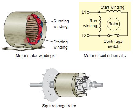
Ill. 43 Split-phase induction motor. Squirrel-cage rotor; Motor stator
windings Motor circuit schematic; Starting winding; Running winding. Motor
circuit schematic; Start winding Centrifugal switch; L1, L2; Run winding;
Rotor
Ill. 44 Rotating magnetic field of a split-phase motor. Start winding;
Run winding; Position 1 Position 2 Position 3
Ill. 45 Centrifugal switch operation. Closed on start; Starting winding;
Run winding
Split-Phase Motor
A single-phase split-phase induction motor uses a squirrel-cage rotor that is identical to that in a three phase motor. Ill. 43 shows the construction and wiring of a split-phase motor. To produce a rotating magnetic field, the single-phase current is split by two windings, the main running winding and an auxiliary starting winding, which is displaced in the stator 90 electrical degrees from the running winding. The starting winding is connected in series with a switch, centrifugally or electrically operated, to disconnect it when the starting speed reaches about 75 % of full-load speed.
Phase displacement is accomplished by the difference in inductive reactance of the start and run windings as well as the physical displacement of the windings in the stator. The starting winding is wound on the top of the stator slots with fewer turns of smaller-diameter wire. The running winding has many turns of large-diameter wire wound in the bottom of the stator slots that give it a higher inductive reactance than the starting winding.
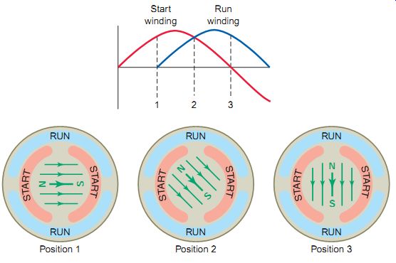
The way in which the two windings of a split-phase motor produce a rotating magnetic field is illustrated in Ill. 44 and can be summarized as follows.
• When AC line voltage is applied, the current in the starting winding leads the current in the running winding by approximately 45 electrical degrees.
• Since the magnetism produced by these currents follows the same wave pattern, the two sine waves can be thought of as the waveforms of the electro magnetism produced by the two windings.
• As the alternations in current (and magnetism) continue, the position of the north and south poles changes in what appears to be a clockwise rotation.
• At the same time the rotating field cuts the squirrel cage conductors of the rotor and induces a current in them.
• This current creates magnetic poles in the rotor, which interact with the poles of the stator rotating magnetic field to produce motor torque.
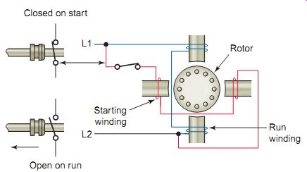
Once the motor is running, the starting winding must be removed from the circuit. Since the starting winding is of a smaller gauge size, continuous current through it would cause the winding to burn out. Either a mechanical centrifugal or electronic solid-state switch may be used to automatically disconnect the starting winding from the circuit. The operation of a centrifugal type switch is illustrated. It consists of a centrifugal mechanism, which rotates on the motor shaft and interacts with a fixed stationary switch whose contacts are connected in series with the start winding.
When the motor approaches its normal operating speed, centrifugal force overcomes the spring force, allowing the contacts to open and disconnect the starting winding from the power source; the motor then continues operating solely on its running winding. Motors using such a centrifugal switch make a distinct clicking noise when starting and stopping as the centrifugal switch opens and closes.
The centrifugal switch can be a source of trouble if it fails to operate properly. Should the switch fail to close when the motor stops, the starting winding circuit will be open. As a result, when the motor circuit is again energized, the motor won’t turn but will simply produce a low humming sound. Normally the starting winding is designed for operation across line voltage for only a short interval during starting. Failure of the centrifugal switch to open within a few seconds of starting may cause the starting winding to char or burn out.
The split-phase induction motor is the simplest and most common type of single-phase motor. Its simple design makes it typically less expensive than other single phase motor types. Split-phase motors are considered to have low or moderate starting torque. Typical sizes range up to about ½ horsepower. Reversing the leads to either the start or run windings, but not to both, changes the direction of rotation of a split-phase motor. Popular applications of split-phase motors include fans, blowers, office machines, and tools such as small saws or drill presses where the load is applied after the motor has obtained its operating speed.
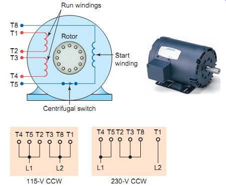
Dual-voltage split-phase motors have leads that allow external connection for different line voltages. Ill. 46 shows a NEMA-standard single-phase motor with dual-voltage run windings. When the motor is operated at low voltage, the two run windings and the start winding are all connected in parallel. For high-voltage operation, the two run windings connect in series and the start winding is connected in parallel with one of the run windings.
Ill. 46 Dual-voltage split-phase motor connections. Leeson, www.leeson.com.
Run windings; Start winding; 115-V CCW 230-V CCW
Ill. 47 Capacitor start motor. Leeson, www.leeson.com. Start winding;
Rotor; Run Start switch; Capacitor
Ill. 48 Two-speed capacitor-start motor wound. Low High; L1 L2 Start
switch, Six-pole run Eight-pole start Eight-pole run, Six-pole start
Ill. 49 Reversible permanent-capacitor motor connection. L1; L2; Reverse;
Forward; Run Auxiliary
Ill. 50 Capacitor-start/capacitor-run motor. Leeson, www.leeson.com.
Run capacitor Start capacitor, Run winding, Auxiliary winding
Split-Phase Capacitor Motor
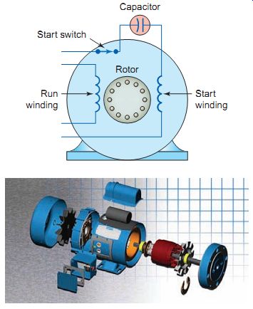
The capacitor-start motor is a modified split-phase motor. A capacitor connected in series with the starting winding creates a phase shift of approximately 80 degrees between the starting and running winding. This is substantially higher than the 45 degrees of a split-phase motor and results in a higher starting torque. Capacitor-start motors provide more than double the starting torque with one-third less starting cur rent than the split-phase motor. Like the split-phase motor, the capacitor start motor also has a starting mechanism, either a mechanical centrifugal switch or solid-state electronic switch. This disconnects not only the start winding, but also the capacitor when the motor reaches about 79% of rated speed.
The capacitor-start motor is more expensive than a comparable split-phase design because of the additional cost of the start capacitor. However, the application range is much wider because of higher starting torque and lower starting current. The job of the capacitor is to improve the starting torque and not the power factor, as it’s only in the circuit for a few seconds at the instant of starting. The capacitor can be a source of trouble if it becomes short circuited or open-circuited. A short-circuited capacitor will cause an excessive amount of current to flow through the staring winding, while an open capacitor will cause the motor to not start.
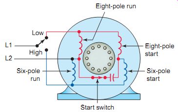
Dual-speed capacitor-start motors have leads that allow external connection for low and high speeds. Ill. 48 shows the wiring diagram for a typical two speed capacitor-start motor wound with two sets of start and run windings. For low-speed 900-rpm operation, the 6-pole set of start and run windings connects to the source and for high-speed 1,200 rpm the eight-pole set is used.
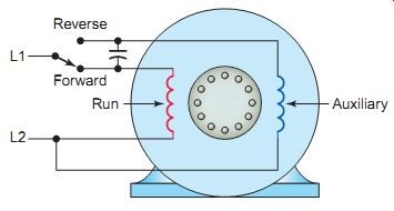
The permanent-capacitor motor has neither a centrifugal switch nor a capacitor strictly for starting. Instead, it has a run-type capacitor permanently connected in series with the start winding. This makes the start winding an auxiliary winding once the motor reaches running speed. Because the run capacitor must be designed for continuous use, it cannot provide the starting boost of the capacitor-start motor. Typical starting torques for permanent-capacitor motors are low, from 30 to 150% of rated load, so these motors are not suited for hard to-start applications.
Permanent-capacitor motors are considered to be the most reliable of the single-phase motors, mostly because no starting switch is needed. The run and auxiliary windings are identical in this type of motor, allowing for the motor to be reversed by switching the capacitor from one winding to the other.
Single-phase motors run in the direction in which they are started, so whichever winding has the capacitor connected to it will control the direction. Permanent split-capacitor motors have a wide variety of applications that include fans, blowers with low starting torque needs, and intermittent cycling uses such as adjusting mechanisms, gate operators, and garage door openers, many of which also need instant reversing. Since the capacitor is used at all times, it also provides improvement of motor power factor.
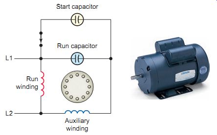
The capacitor-start/capacitor-run motor , uses both start and run capacitors located in the housing connected to the top of the motor. When the motor is started the two capacitors are connected in parallel to produce a large amount of capacitance and starting torque. Once the motor is up to speed, the start switch disconnects the start capacitor from the circuit. The motor start capacitor is typically an electrolytic type, while the run capacitor is an oil-filled type. The electrolytic type offers a large amount of capacitance when compared to its oil-filled counterpart. It’s important to note that these two capacitors are not interchangeable, as an electrolytic capacitor used in an AC circuit for more than a few seconds will overheat.
Capacitor start/capacitor run motors operate at lower full-load currents and higher efficiency. Among other things, this means they run at lower temperature than other single-phase motor types of comparable horse power. Their main disadvantage is a higher price, which is mostly the result of more capacitors, plus a starting switch. Capacitor start/capacitor run motors are used over a wide range of single-phase applications, primarily starting hard loads that include woodworking machinery, air compressors, high-pressure water pumps, vacuum pumps and other high-torque applications. They are avail able in sizes from ½ to 25 horsepower.
Shaded-Pole Motor
Unlike other types of single-phase motors, shaded-pole motors have only one main winding and no start winding or switch. As in other induction motors, the rotating part is a squirrel-cage rotor. Starting is by means of a design that uses a continuous copper loop around a small portion of each motor pole. Currents in this copper loop delay the phase of magnetic flux in that part of the pole enough to provide a rotating field. This rotating field effect produces a very low starting torque compared to other classes of single-phase motors. Although direction of rotation is not normally reversible, some shaded-pole motors are wound with two main windings that reverse the direction of the field. Slip in the shaded-pole motor is not a problem, as the current in the stator is not controlled by a counter-voltage determined by rotor speed, as in other types of single-phase motors. Speed can therefore be controlled merely by varying voltage, or through a multitap winding.
Shaded-pole motors are best suited to low-power household application, because the motors have low starting torque and efficiency ratings. Because of the weak starting torque, shaded-pole motors are built only in small sizes ranging from 1/20 to 1/6 hp. Applications for this type of motor include fans, can openers, blowers, and electric razors.
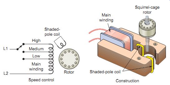
Ill. 51 Shaded-pole motor. Construction Main winding Squirrel-cage rotor
Shaded-pole coil Speed control Rotor Shaded pole coil High Medium Low
Main winding
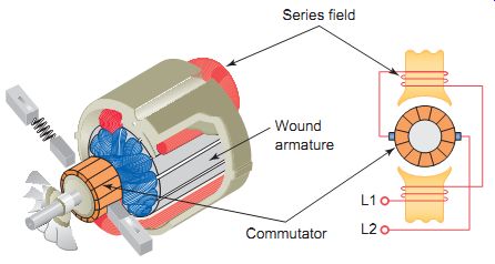
Ill. 52 Universal motor. Universal Motor. L L; Commutator; Wound armature;
Series field
The universal motor is constructed like a series-type DC motor with a wound series field (on the stator) and a wound armature (on the rotor). As in the DC series motor, its armature and field coils are connected in series. As the name implies, universal motors can be operated with either direct cur rent or single-phase alternating current. The reason for this is that a DC motor will continue to turn in the same direction if the current through the armature and field are reversed at the same time. This is exactly what hap pens when the motor is connected to an AC source. Universal motors are also known as AC series motors or AC commutator motors.
Although universal motors are designed to run on AC or DC, most are used for household appliances and portable hand tools that operate on single-phase AC power.
Unlike other types of single-phase motors, universal motors can easily exceed one revolution per cycle of the main current. This makes them useful for appliances such as blenders, vacuum cleaners, and hair dryers, where high-speed operation is desired. The speed of the universal motor, like that of DC series motor, varies considerably from no load to full load, as can be observed when you apply varying pressure on an universal drill motor.
Both the speed and direction of rotation of a universal motor can be controlled.
Reversing is accomplished just as in a DC series motor by reversing the current flow through the armature with respect to the series field. Varying the voltage that is applied to the motor controls the speed.
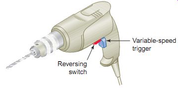
Ill. 53 Motor speed and direction controls. Reversing switch; Variable-speed
trigger
QUIZ:
1. What is the major difference between the starting requirements for a three-phase and a single-phase induction motor?
2. a. Outline the starting sequence for a split-phase induction motor.
b. How is its direction of rotation reversed?
3. Dual-voltage split-phase motors have leads that allow external connection for different line voltages.
How are the start and run windings connected for high and low line voltages?
4. What is the main advantage of capacitor motors over split-phase types?
5. Name the three types of capacitor motor designs.
6. Explain how the shaded-pole motor is started.
7. What type of DC motor is constructed like a universal motor?
Cont. to part 5