AMAZON multi-meters discounts AMAZON oscilloscope discounts
Cont. from part 2
Three-Phase Alternating Current Motors
Rotating Magnetic Field
The main difference between AC and DC motors is that the magnetic field generated by the stator rotates in the case of AC motors. A rotating magnetic field is key to the operation of all AC motors. The principle is simple. A magnetic field in the stator is made to rotate electrically around and around in a circle. Another magnetic field in the rotor is made to follow the rotation of this field pattern by being attracted and repelled by the stator field. Because the rotor is free to turn, it follows the rotating magnetic field in the stator.
Ill. 31 illustrates the concept of a rotating magnetic field as it applies to the stator of a three-phase AC motor. The operation can be summarized as follows:
• Three sets of windings are placed 120 electrical degrees apart with each set connected to one phase of the three-phase power supply.
• When three-phase current passes through the stator windings, a rotating magnetic field effect is produced that travels around the inside of the stator core.
• Polarity of the rotating magnetic field is shown at six selected positions marked off at 60 degree intervals on the sine waves representing the current flowing in the three phases, A, B, and C.
• In the example shown, the magnetic field will rotate around the stator in a clockwise direction.
• Simply interchanging any two of the three-phase power input leads to the stator windings reverses direction of rotation of the magnetic field.
• The number of poles is determined by how many times a phase winding appears. In this example, each winding appears twice, so this is a two-pole stator.
There are two ways to define AC motor speed. First is synchronous speed. The synchronous speed of an AC motor is the speed of the stator's magnetic field rotation. This is the motor's ideal theoretical, or mathematical, speed, since the rotor will always turn at a slightly slower rate. The other way motor speed is measured is called actual speed. This is the speed at which the shaft rotates. The nameplate of most AC motors lists the actual motor speed rather than the synchronous speed.
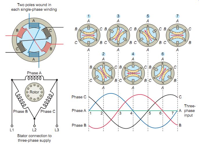
Ill. 31 Rotating magnetic field. Two poles wound in each single-phase
winding. Stator connection to three-phase supply. Three-phase input.
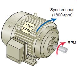
Ill. 32 Synchronous and actual speed. (1800-rpm) RPM; Synchronous
===
EXAMPLE 3-- Problem: Determine the synchronous speed of a four pole AC motor connected to a 60-Hz electrical supply. Solution: S = 120 f/P = 120 × 60 /4 = 1,800 rpm
===
The speed of the rotating magnetic field varies directly with the frequency of the power supply and inversely with the number of poles constructed on the stator winding. This means the higher the frequency, the greater the speed and the greater the number of poles the slower the speed.
Motors designed for 60 Hz use have synchronous speeds of 3,600, 1,800, 1,200, 900, 720, 600, 514, and 450 rpm.
The synchronous speed of an AC motor can be calculated by the formula:
S = 120 f / P
where
S = synchronous speed in rpm
f = frequency, Hz, of the power supply
P = number of poles wound in each of the single-phase windings
Induction Motor
The AC induction motor is by far the most commonly used motor because it’s relatively simple and can be built at less cost than other types. Induction motors are made in both three-phase and single-phase types. The induction motor is so named because no external voltage is applied to its rotor. There are no slip rings or any DC excitation supplied to the rotor. Instead, the AC current in the stator induces a voltage across an air gap and into the rotor winding to produce rotor current and associated magnetic field. The stator and rotor magnetic fields then interact and cause the rotor to turn.
A three-phase motor stator winding consists of three separate groups of coils, called phases, and designated A, B, and C. The phases are displaced from each other by 120 electrical degrees and contain the same number of coils, connected for the same number of poles. Poles refer to a coil or group of coils wound to produce a unit of magnetic polarity. The number of poles a stator is wound for will always be an even number and refers to the total number of north and south poles per phase. Ill. 34 shows a typical connection of coils for a four-pole, three phase Y-connected induction motor.
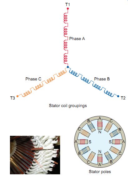
Ill. 34 Stator coils for a Y-connected four-pole, three-phase inductor
motor. Stator coil groupings; Stator poles;
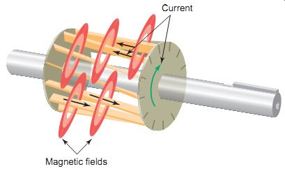
Ill. 33 Induced rotor current. Magnetic fields; Current
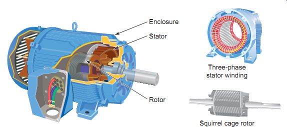
Ill. 35 Squirrel-cage induction motor. Enclosure; Stator; Rotor
Three-phase stator winding; Squirrel cage rotor
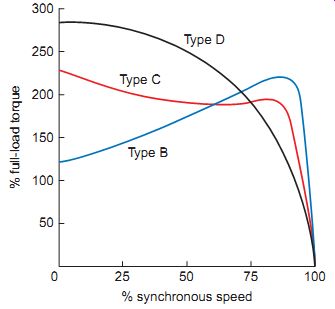
Ill. 36 Typical squirrel-cage motor speed-torque characteristics. % full-load
torque; % synchronous speed
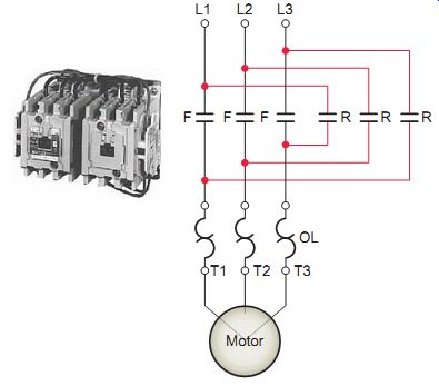
Ill. 37 Power circuit for reversing a three-phase motor.
Squirrel Cage Induction Motor
An induction motor rotor can be either wound rotor or a squirrel cage rotor. The majority of commercial and industrial applications usually involve the use of a three-phase squirrel-cage induction motor. A typical squirrel-cage induction motor is shown. The rotor is constructed using a number of single bars short-circuited by end rings and arranged in a hamster-wheel or squirrel-cage configuration. When voltage is applied to the stator winding, a rotating magnetic field is established. This rotating magnetic field causes a voltage to be induced in the rotor, which, because the rotor bars are essentially single-turn coils, causes currents to flow in the rotor bars. These rotor currents establish their own magnetic field, which interacts with the stator magnetic field to produce a torque. The resultant production of torque spins the rotor in the same direction as the rotation of the magnetic field produced by the stator. In modern induction motors, the most common type of rotor has cast-aluminum conductors and short-circuiting end rings.
The resistance of the squirrel-cage rotor has an important effect on the operation of the motor. A high-resistance rotor develops a high starting torque at low starting cur rent. A low-resistance rotor develops low slip and high efficiency at full load. Ill. 36 shows how motor torque varies with rotor speed for three NEMA-type squirrel-cage induction motors:
NEMA Design B - Considered a standard type with normal starting torque, low starting current, and low slip at full load. Suitable for a broad variety of applications, such as fans and blowers, that require normal starting torque.
NEMA Design C -This type has higher than standard rotor resistance, which improves the rotor power factor at start, providing more starting torque. When loaded, however, this extra resistance causes a greater amount of slip. Used for equipment, such as a pump, that requires a high starting torque.
NEMA Design D -The even higher rotor resistance of this type produces a maximum amount of starting torque. This type is suitable for equipment with very high inertia starts such as cranes and hoists.
Operating characteristics of the squirrel-cage motor include the following:
• The motor normally operates at essentially constant speed, close to the synchronous speed.
• Large starting currents required by this motor can result in line voltage fluctuations.
• Interchanging any two of the three main power lines to the motor reverses the direction of rotation.
Ill. 37 shows the power circuit for reversing a three-phase motor. The forward contacts F, when closed, connect L1, L2, and L3 to motor terminals T1, T2, and T3, respectively. The reverse contacts R, when closed, connect L1, L2, and L3 to motor terminals T3, T2, and T1, respectively, and the motor will now run in the opposite direction.
• Once started, the motor will continue to run, with a phase loss, as a single-phase motor. The current drawn from the remaining two lines will almost double, and the motor will overheat. The motor won’t start from standstill if it has lost a phase.
The rotor does not revolve at synchronous speed, but tends to slip behind. Slip is what allows a motor to turn.
If the rotor turned at the same speed at which the field rotates, there would be no relative motion between the rotor and the field and no voltage induced. Because the rotor slips with respect to the rotating magnetic field of the stator, voltage and current are induced in the rotor.
The difference between the speed of the rotating magnetic field and the rotor in an induction motor is known as slip and is expressed as a percentage of the synchronous speed as follows:
Percent slip = [Synchronous speed - Actual speed / Synchronous speed ] × 100
The slip increases with load and is necessary to produce useful torque. The usual amount of slip in a 60-Hz, three-phase motor is 2 or 3 %.
===
Problem: Determine the percent slip of an induction motor having a synchronous speed of 1,800 rpm and a rated actual speed of 1,750 rpm.
Solution: Percent slip = Synchronous speed - Actual speed/Synchronous speed × 100 = 1,800 - 1,750/ 1,800 × 100 = 2.78%
===
Loading of an induction motor is similar to that of a transformer in that the operation of both involves changing flux linkages with respect to a primary (stator) winding and secondary (rotor) winding. The no-load current is low and similar to the exciting current in a transformer.
Thus, it’s composed of a magnetizing component that creates the revolving flux and a small active component that supplies the windage and friction losses in the rotor plus the iron losses in the stator. When the induction motor is under load, the rotor current develops a flux that opposes and, therefore, weakens the stator flux. This allows more current to flow in the stator windings, just as an increase in the current in the secondary of a transformer results in a corresponding increase in the primary current.
You may recall that power factor (PF) is defined as the ratio of the actual (or true) power (watts) to the apparent power (volt-amperes) and is a measure of how effectively the current drawn by a motor is converted into useful work. The motor exciting current and reactive power under load remain about the same as at no load. For this reason, whenever a motor is operating with no load, the power factor is very low in comparison to when it’s operating at full load. At full load the PF ranges from 70% for small motors to 90 % for larger motors.
Induction motors operate at their peak efficiency if they are sized correctly for the load that they will drive. Over sized motors not only operate inefficiently, but they also carry a higher first cost than right-sized units.
The moment a motor is started, during the acceleration period, the motor draws a high inrush current. This inrush current is also called the locked-rotor current. Common induction motors, started at rated voltage, have locked-rotor starting currents of up to 6 times their nameplate full load current. The locked-rotor current depends largely on the type of rotor bar design and can be determined from the NEMA design code letters listed on the nameplate.
High locked-rotor motor current can create voltage sags or dips in the power lines, which may cause objectionable light flicker and problems with other operating equipment. Also, a motor that draws excessive current under locked-rotor conditions is more likely to cause nuisance tripping of protection devices during motor start-ups.
A single-speed motor has one rated speed at which it runs when supplied with the nameplate voltage and frequency. A multispeed motor will run at more than one speed, depending on how the windings are connected to form a different number of magnetic poles. Two-speed, single-winding motors are called consequent pole motors. The low speed on a single-winding consequent pole motor is always one-half of the higher speed. If requirements dictate speeds of any other ratio, a two winding motor must be used. With separate winding motors a separate winding is installed in the motor for each desired speed.
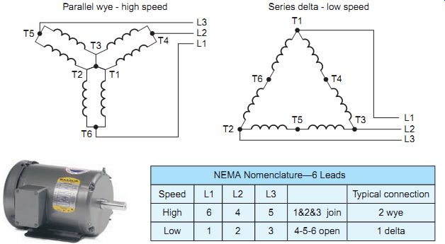
Ill. 38 Dual-speed, three-phase squirrel-cage single-winding motor. Baldor
Electric Company. baldor.com. Series delta - low speed; Parallel wye -
high speed
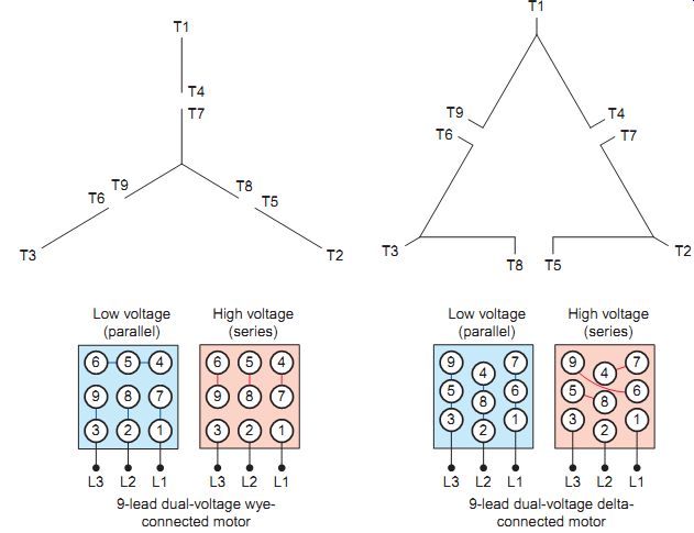
Ill. 39 Typical connections for dual-voltage wye and delta series and
parallel reconnections. Low voltage (parallel); High voltage (series).
9-lead dual-voltage wye connected motor.
Consequent pole single-winding motors have their stator windings arranged so that the number of poles can be changed by reversing some of the coil currents.
Ill. 38 shows a dual-speed three-phase squirrel-cage single-winding motor with six stator leads brought out.
By making the designated connections to these leads, the windings can be connected in series delta or parallel wye.
The series delta connection results in low speed and the parallel wye in high speed. The torque rating would be the same at both speeds. If the winding is such that the series delta connection gives the high speed and the parallel wye connection the low speed, the horsepower rating is the same at both speeds.
Single-speed AC induction motors are frequently supplied with multiple external leads for various voltage ratings in fixed-frequency applications. The multiple leads may be designed to allow either series to parallel reconnections, wye to delta reconnections, or combinations of these.
Ill. 39 shows typical connections for dual-voltage wye and delta series and parallel reconnections. These types of reconnections should not be confused with the reconnection of multispeed polyphase induction motors. In the case of multispeed motors, the reconnection results in a motor with a different number of magnetic poles and therefore a different synchronous speed at a given frequency.
Wound-Rotor Induction Motor
The wound-rotor induction motor (sometimes called a slip-ring motor) is a variation on the standard cage induction motors. Wound-rotor motors have a three-phase winding wound on the rotor, which is terminated to slip rings. The operation of the motor can be summarized as follows.
• The rotor slip rings connect to start-up resistors in order to provide current and speed control on start-up.
• When the motor is started, the frequency of current flowing through the rotor windings is nearly 60 Hz.
• Once up to full speed, the rotor current frequency drops down below 10 Hz to nearly a DC signal.
• The motor is normally started with full external resistance in the rotor circuit that is gradually reduced to zero, either manually or automatically.
• This results in a very high starting torque from zero speed to full speed at a relatively low starting current.
• With zero external resistance, the wound-rotor motor characteristics approach those of the squirrel cage motor.
• Interchanging any two stator voltage supply leads reverses the direction of rotation.
A wound-rotor motor is used for constant-speed applications requiring a heavier starting torque than is obtain able with the squirrel-cage type. With a high-inertia load a standard cage induction motor may suffer rotor damage on starting due to the power dissipated by the rotor. With the wound rotor motor, the secondary resistors can be selected to provide the optimum torque curves and they can be sized to withstand the load energy without failure. Starting a high-inertia load with a standard cage motor would require between 400 and 550 % start current for up to 60 seconds. Starting the same machine with a wound-rotor motor (slip-ring motor) would require around 200 % current for around 20 seconds. For this reason, wound rotor types are frequently used instead of the squirrel-cage types in larger sizes.
Wound-rotor motors are also used for variable-speed service. To use a wound-rotor motor as an adjustable-speed drive, the rotor control resistors must be rated for continuous current. If the motor is used only for a slow acceleration or high starting torque but then operates at its maximum speed for the duration of the work cycle, then the resistors will be removed from the circuit when the motor is at rated speed.
In that case they will have been duty cycle-rated for starting duty only. Speed varies with this load, so that they should not be used where constant speed at each control setting is required, as for machine tools.
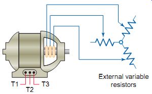
Ill. 40 Wound-rotor induction motor. External variable resistors
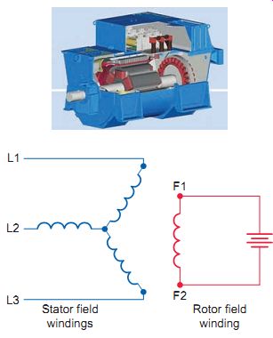
Ill. 41 Three-phase synchronous motor. ABB, www.abb.com. Stator field
windings; Rotor field winding
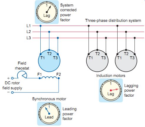
Ill. 42 Synchronous motor used to correct power factor. System corrected
power factor. Three-phase distribution system. Leading power factor; Field
rheostat; DC rotor field supply
Three-Phase Synchronous Motor
The three-phase synchronous motor is a unique and specialized motor. As the name suggests, this motor runs at a constant speed from no load to full load in synchronism with line frequency. As in squirrel-cage induction motors, the speed of a synchronous motor is determined by the number of pairs of poles and the line frequency.
A typical three-phase synchronous motor is shown in Ill. 41.The operation of the motor can be summarized as follows.
• Three-phase AC voltage is applied to the stator windings and a rotating magnetic field is produced.
• DC voltage is applied to the rotor winding and a second magnetic field is produced.
• The rotor then acts like a magnet and is attracted by the rotating stator field.
• This attraction exerts a torque on the rotor and causes it to rotate at the synchronous speed of the rotating stator field.
• The rotor does not require the magnetic induction from the stator field for its excitation. As a result, the motor has zero slip compared to the induction motor, which requires slip in order to produce torque.
Synchronous motors are not self-starting and therefore require a method of bringing the rotor up to near synchro nous speed before the rotor DC power is applied. Synchronous motors typically start as a normal squirrel cage induction motor through use of special rotor amortisseur windings. Also, there are two basic methods of providing excitation current to the rotor. One method is to use an external DC source with current supplied to the windings through slip rings. The other method is to have the exciter mounted on the common shaft of the motor. This arrangement does not require the use of slip rings and brushes.
An electrical system's lagging power factor can be corrected by overexciting the rotor of a synchronous motor operating within the same system. This will produce a leading power factor, canceling out the lagging power factor of the inductive loads. An underexcited DC field will produce a lagging power factor and for this reason is seldom used. When the field is normally excited, the synchronous motor will run at a unity power factor. Three-phase synchronous motors can be used for power factor correction while at the same time performing a major function, such as operating a compressor. If mechanical power output is not needed, however, or can be provided in other cost-effective ways, the synchronous machine remains useful as a "nonmotor" means of con trolling power factor. It does the same job as a bank of static capacitors. Such a machine is called a synchronous condenser or capacitor.
QUIZ:
1. A rotating magnetic field is the key to the operation of AC motors. Give a brief explanation of its principle of operation.
2. Compare synchronous speed and actual speed of an AC motor.
3. Calculate the synchronous speed of a six-pole AC motor operated from a standard voltage source.
4. Why is the induction motor so named?
5. Outline the operating principle of a three-phase squirrel-cage induction motor.
6. Explain what effect rotor resistance has on the operation of a squirrel-cage induction motor.
7. How is the direction of rotation of a squirrel-cage motor reversed?
8. If, while a three-phase induction motor is operating, power to one phase of its squirrel cage is lost, what will happen?
9. Define the term slip as it applies to an induction motor.
10. Calculate the percent slip of an induction motor having a synchronous speed of 3,600 rpm and a rated actual speed of 3,435 rpm.
11. What effect does loading have on the power factor of an AC motor?
12. What is the typical value of the locked-rotor motor current?
13. How is the speed of an induction motor determined?
14. Explain the difference between multispeed consequent pole and separate winding induction motors.
15. A wound-rotor induction motor is normally started with full external resistance in the rotor circuit that is gradually reduced to zero. How does this affect starting torque and current?
16. How is the direction of rotation of a wound-rotor induction motor changed?
17. When a wound-rotor motor is used as an adjustable speed drive, rather than only for starting purposes, what must the duty cycle of the rotor resistors be rated for?
18. State two advantages of using three-phase synchronous motor drives in an industrial plant.