AMAZON multi-meters discounts AMAZON oscilloscope discounts
(cont. from part 1)
Nonceramic (Composite) Insulators
Nonceramic insulators use polymers instead of porcelain. High-voltage composite insulators are built with mechanical load-bearing fiberglass rods, which are covered by polymer weather sheds to assure high electrical strength.
The first insulators were built with bisphenol epoxy resin in the mid-1940s and are still used in indoor applications. Cycloaliphatic epoxy resin insulators were introduced in 1957. Rods with weather sheds were molded and cured to form solid insulators. These insulators were tested and used in England for several years. Most of them were exposed to harsh environmental stresses and failed. However, they have been successfully used indoors. The first composite insulators, with fiberglass rods and rubber weather sheds, appeared in the mid-1960s. The advantages of these insulators are as follows [5-7]:
• Lightweight, which lowers construction and transportation costs
• More vandalism resistant
• Higher strength-to-weight ratio, allowing longer design spans
• Better contamination performance
• Improved transmission line aesthetics, resulting in better public acceptance of a new line However, early experiences were discouraging because several failures were observed during operation.
Typical failures experienced were:
• Tracking and erosion of the shed material, which led to pollution and caused flashover
• Chalking and crazing of the insulator's surface, which resulted in increased contaminant collection, arcing, and flashover
• Reduction of contamination flashover strength and subsequent increased contamination-induced flashover
• Deterioration of mechanical strength, which resulted in confusion in the selection of mechanical line loading
• Loosening of end fittings
• Bonding failures and breakdowns along the rod-shed interface
• Water penetration followed by electrical failure
As a consequence of reported failures, an extensive research effort led to second- and third-generation nonceramic transmission line insulators. These improved units have tracking-free sheds, better corona resistance, and slip-free end fittings. A better understanding of failure mechanisms and of mechanical strength-time dependency has resulted in newly designed insulators that are expected to last 20-30 years [8,9]. Increased production quality control and automated manufacturing technology has further improved the quality of these third-generation nonceramic transmission line insulators.
--3.1 Composite Suspension Insulators
A cross section of a third-generation composite insulator is shown in FIG. 10. The major components of a composite insulator are
• End fittings
• Corona ring(s)
• Fiberglass-reinforced plastic rod
• Interface between shed and sleeve
• Weather shed
===
End fitting Silicone weathersheds Fiberglass rod impregnated in a resin The interfaces between the different materials Lower grading ring 230 kV and above Crimped end End fitting
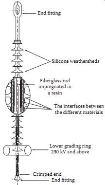
Above: FIG. 10 Cross section of a typical composite insulator. (From Toughened
Glass Insulators, Sediver, Inc., Nanterre, France, 1993.)
===
--3.1.1 End Fittings
End fittings connect the insulator to a tower or conductor. It’s a heavy metal tube with an oval eye, socket, ball, tongue, and a clevis ending. The tube is attached to a fiberglass rod. The duty of the end fit ting is to provide a reliable, nonslip attachment without localized stress in the fiberglass rod. Different manufacturers use different technologies. Some methods are as follows:
1. The ductile galvanized iron-end fitting is wedged and glued with epoxy to the rod.
2. The galvanized forged steel-end fitting is swaged and compressed to the rod.
3. The malleable cast iron, galvanized forged steel, or aluminous bronze-end fitting is attached to the rod by controlled swaging. The material is selected according to the corrosion resistance requirement. The end-fitting coupling zone serves as a mechanical fuse and determines the strength of the insulator.
4. High-grade forged steel or ductile iron is crimped to the rod with circumferential compression.
The interface between the end fitting and the shed material must be sealed to avoid water penetration.
Another technique, used mostly in distribution insulators, involves the weather shed overlapping the end fitting.
--3.1.2 Corona Ring(s)
Electrical field distribution along a nonceramic insulator is nonlinear and produces very high elec tric fields near the end of the insulator. High fields generate corona and surface discharges, which are the source of insulator aging. Above 230 kV, each manufacturer recommends aluminum corona rings be installed at the line end of the insulator. Corona rings are used at both ends at higher volt ages (>500 kV).
--3.1.3 Fiberglass-Reinforced Plastic Rod
The fiberglass is bound with epoxy or polyester resin. Epoxy produces better-quality rods but poly ester is less expensive. The rods are manufactured in a continuous process or in a batch mode, producing the required length. The even distribution of the glass fibers assures equal loading, and the uniform impregnation assures good bonding between the fibers and the resin. To improve quality, some manufacturers use E-glass to avoid brittle fractures. Brittle fracture can cause sudden shattering of the rod.
--3.1.4 Interfaces between Shed and Fiberglass Rod
Interfaces between the fiberglass rod and weather shed should have no voids. This requires an appropriate interface material that assures bonding of the fiberglass rod and weather shed. The most frequently used techniques are as follows:
1. The fiberglass rod is primed by an appropriate material to assure the bonding of the sheds.
2. Silicon rubber or ethylene propylenediene monomer (EPDM) sheets are extruded onto the fiber glass rod, forming a tube-like protective covering.
3. The gap between the rod and the weather shed is filled with silicon grease, which eliminates voids.
--3.1.5 Weather Shed
All high-voltage insulators use rubber weather sheds installed on fiberglass rods. The interface between the weather shed, fiberglass rod, and the end fittings is carefully sealed to prevent water penetration. The most serious insulator failure is caused by water penetration to the interface.
The most frequently used weather shed technologies are as follows:
1. Ethylene propylene copolymer (EPM) and silicon rubber alloys, where hydrated-alumina fillers are injected into a mold and cured to form the weather sheds. The sheds are threaded to the fiberglass rod under vacuum. The inner surface of the weather shed is equipped with O-ring-type grooves filled with silicon grease that seals the rod-shed interface. The gap between the end fit tings and the sheds is sealed by axial pressure. The continuous slow leaking of the silicon at the weather shed junctions prevents water penetration.
2. High-temperature vulcanized (HTV) silicon rubber sleeves are extruded on the fiberglass surface to form an interface. The silicon rubber weather sheds are injection-molded under pressure and placed onto the sleeved rod at a predetermined distance. The complete subassembly is vulcanized at high temperatures in an oven. This technology permits the variation of the distance between the sheds.
3. The sheds are directly injection molded under high pressure and high temperature onto the primed rod assembly. This assures simultaneous bonding to both the rod and the end fittings.
Both EPDM and silicon rubber are used. This one-piece molding assures reliable sealing against moisture penetration.
4. One piece of silicon or EPDM rubber shed is molded directly to the fiberglass rod. The rubber contains fillers and additive agents to prevent tracking and erosion.
--3.2 Composite Post Insulators
The construction and manufacturing method of post insulators is similar to that of suspension insulators. The major difference is in the end fittings and the use of a larger diameter fiberglass rod. The latter is necessary because bending is the major load on these insulators. The insulators are flexible, which permits bending in case of sudden overload. A typical post-type insulator used for 69 kV lines is shown in FIG. --
Post-type insulators are frequently used on transmission lines. Development of station-type post insulators has just begun. The major problem is the fabrication of high strength, large diameter fiber glass tubes and sealing of the weather shed.
==
Injection molded EPDM rubber covering and weathersheds Fiberglass reinforced resin rod End fitting joined to rod by compression process Malleable iron end fitting; outer surfaces galvanized for corrosion protection
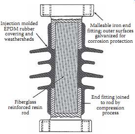
Above: FIG. 11 Post-type composite insulator. (From Toughened Glass Insulators,
Sediver, Inc., Nanterre, France, 1993.)
===
Insulator Failure Mechanism
--4.1 Porcelain Insulators
Cap-and-pin porcelain insulators are occasionally destroyed by direct lightning strikes, which generate a very steep wave front. Steep-front waves break down the porcelain in the cap, cracking the porcelain.
The penetration of moisture results in leakage currents and short circuits of the unit.
Mechanical failures also crack the insulator and produce short circuits. The most common cause is water absorption by the Portland cement used to attach the cap to the porcelain. Water absorption expands the cement, which in turn cracks the porcelain. This reduces the mechanical strength, which may cause separation and line dropping.
Short circuits of the units in an insulator string reduce the electrical strength of the string, which may cause flashover in polluted conditions.
Glass insulators use alumina cement, which reduces water penetration and the head-cracking problem.
A great impact, such as a bullet, can shatter the shell, but won’t reduce the mechanical strength of the unit.
The major problem with the porcelain insulators is pollution, which may reduce the flashover volt age under the rated voltages. Fortunately, most areas of the United States are lightly polluted. However, some areas with heavy pollution experience flashover regularly.
--4.2 Insulator Pollution
Insulation pollution is a major cause of flashovers and of long-term service interruptions. Lightning caused flashovers produce short circuits. The short-circuit current is interrupted by the circuit breaker and the line is reclosed successfully. The line cannot be successfully reclosed after pollution-caused flashover because the contamination reduces the insulation's strength for a long time. Actually, the insulator must dry before the line can be reclosed.
--4.2.1 Ceramic Insulators
Pollution-caused flashover is an involved process that begins with the pollution source. Some sources of pollution are salt spray from an ocean, salt deposits in the winter, dust and rubber particles during the summer from highways and desert sand, industrial emissions, engine exhaust, fertilizer deposits, and generating station emissions. Contaminated particles are carried in the wind and deposited on the insulator's surface. The speed of accumulation is dependent upon wind speed, line orientation, particle size, material, and insulator shape. Most of the deposits lodge between the insulator's ribs and behind the cap because of turbulence in the airflow in these areas ( FIG. 12).
The deposition is continuous, but is interrupted by occasional rain. Rain washes the pollution away and high winds clean the insulators. The top surface is cleaned more than the ribbed bottom. The horizontal and V strings are cleaned better by the rain than the I strings. The deposit on the insulator forms a well-dispersed layer and stabilizes around an average value after longer exposure times. However, this average value varies with the changing of the seasons.
Fog, dew, mist, or light rain wets the pollution deposits and forms a conductive layer. Wetting is dependent upon the amount of dissolvable salt in the contaminant, the nature of the insoluble material, duration of wetting, surface conditions, and the temperature difference between the insulator and its surroundings. At night, the insulators cool down with the low night temperatures. In the early morning, the air temperature begins increasing, but the insulator's temperature remains constant. The tempera ture difference accelerates water condensation on the insulator's surface. Wetting of the contamination layer starts leakage currents.
Leakage current density depends upon the shape of the insulator's surface. Generally, the highest current density is around the pin. The current heats the conductive layer and evaporates the water at the areas with high current density. This leads to the development of dry bands around the pin. The dry bands modify the voltage distribution along the surface. Because of the high resistance of the dry bands, it’s across them that most of the voltages will appear. The high voltage produces local arcing. Short arcs ( FIG. 13) will bridge the dry bands.
Leakage current flow will be determined by the voltage drop of the arcs and by the resistance of the wet layer in series with the dry bands. The arc length may increase or decrease, depending on the layer resistance. Because of the large layer resistance, the arc first extinguishes, but further wetting reduces the resistance, which leads to increases in arc length. In adverse conditions, the level of contamination is high and the layer resistance becomes low because of intensive wetting. After several arcing periods, the length of the dry band will increase and the arc will extend across the insulator. This contamination causes flashover.
In favorable conditions when the level of contamination is low, layer resistance is high and arcing continues until the sun or wind dries the layer and stops the arcing. Continuous arcing is harmless for ceramic insulators, but it ages nonceramic and composite insulators.
The mechanism described above shows that heavy contamination and wetting may cause insulator flashover and service interruptions. Contamination in dry conditions is harmless. Light contamination and wetting causes surface arcing and aging of nonceramic insulators.
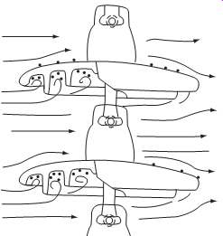
Above: FIG. 12 Deposit accumulation. (From Application Guide for Composite
Suspension Insulators, Sediver, Inc., York, SC, 1993. )
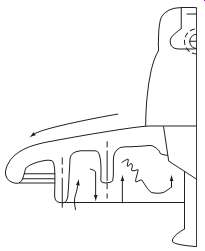
Above: FIG. 13 Dry-band arcing. (From Application Guide for Composite Suspension
Insulators, Sediver, Inc., York, SC, 1993.)
===
Equivalent salt deposit density (ESDD) in mg/cm2 Electrical stress in kV/cm
Silicone hydrophobic Porcelain Silicone hydrophibic EPDM
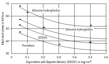
Above: FIG. 14 Surface electrical stress vs. ESDD of fully wetted insulators
(laboratory test results). (From Application Guide for Composite Suspension
Insulators, Sediver, Inc., York, SC, 1993. )
===
TABLE --6 Number of Standard Insulators for Contaminated Areas
System Voltage KV Level of Contamination Very Light Light Moderate Heavy
==
Mechanical Electrical Gunshot Deterioration Cause of failure
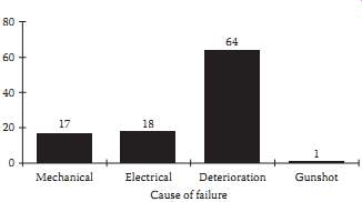
Above: FIG. 15 Cause of composite insulator failure. (From Schneider, H.
et al., IEEE Trans. Power Del. 4(4), 2214, 1989.)
===
--4.2.2 Nonceramic Insulators
Nonceramic insulators have a dirt- and water-repellent (hydrophobic) surface that reduces pollution accumulation and wetting. The different surface properties slightly modify the flashover mechanism.
Contamination buildup is similar to that in porcelain insulators. However, nonceramic insulators tend to collect less pollution than ceramic insulators. The difference is that in a composite insulator, the diffusion of low-molecular-weight silicone oil covers the pollution layer after a few hours. Therefore, the pollution layer will be a mixture of the deposit (dust, salt) and silicone oil. A thin layer of silicone oil, which provides a hydrophobic surface, will also cover this surface.
Wetting produces droplets on the insulator's hydrophobic surface. Water slowly migrates to the pollution and partially dissolves the salt in the contamination. This process generates high resistivity in the wet region. The connection of these regions starts leakage current. The leakage current dries the surface and increases surface resistance. The increase of surface resistance is particularly strong on the shaft of the insulator where the current density is higher.
Electrical fields between the wet regions increase. These high electrical fields produce spot discharges on the insulator's surface. The strongest discharge can be observed at the shaft of the insulator. This discharge reduces hydrophobicity, which results in an increase of wet regions and an intensification of the discharge. At this stage, dry bands are formed at the shed region. In adverse conditions, this phenomenon leads to flashover. However, most cases of continuous arcing develop as the wet and dry regions move on the surface.
The presented flashover mechanism indicates that surface wetting is less intensive in nonceramic insulators. Partial wetting results in higher surface resistivity, which in turn leads to significantly higher flashover voltage. However, continuous arcing generates local hot spots, which cause aging of the insulators.
--4.3 Effects of Pollution
The flashover mechanism indicates that pollution reduces flashover voltage. The severity of flashover voltage reduction is shown in FIG. 14. This figure shows the surface electrical stress (field), which causes flashover as a function of contamination, assuming that the insulators are wet. This means that the salt in the deposit is completely dissolved. The ESDD describes the level of contamination.
These results show that the electrical stress, which causes flashover, decreases by increasing the level of pollution on all of the insulators. This figure also shows that nonceramic insulator performance is better than ceramic insulator performance. The comparison between EPDM and silicone shows that flashover performance is better for the latter.
Table --6 shows the number of standard insulators required in contaminated areas. This table can be used to select the number of insulators, if the level of contamination is known.
Pollution and wetting cause surface discharge arcing, which is harmless on ceramic insulators, but produces aging on composite insulators. Aging is a major problem and will be discussed in the next section.
--4.4 Composite Insulators
The Electric Power Research Institute (EPRI) conducted a survey analyzing the cause of composite insulator failures and operating conditions. The survey was based on the statistical evaluation of failures reported by utilities.
Results show that a majority of insulators (48%) are subjected to very light pollution and only 7% operate in heavily polluted environments. FIG. 15 shows the typical cause of composite insulator failures. The majority of failures are caused by deterioration and aging. Most electrical failures are caused by water penetration at the interface, which produces slow tracking in the fiberglass rod surface.
This tracking produces a conduction path along the fiberglass surface and leads to internal breakdown of the insulator. Water penetration starts with corona or erosion-produced cuts, holes on the weather shed, or mechanical load-caused separation of the end-fitting and weather shed interface.
Most of the mechanical failures are caused by breakage of the fiberglass rods in the end fitting. This occurs because of local stresses caused by inappropriate crimping. Another cause of mechanical failures is brittle fracture. Brittle fracture is initiated by the penetration of water containing slight acid from pollution. The acid may be produced by electrical discharge, initiate chemical reactions which attracts bonds in the glass-fiber. This cutting of the bonds causes smooth fracture of the glass-fiber rod.
The brittle fractures start at high mechanical stress points, many times in the end fitting.
--4.5 Aging of Composite Insulators
Most technical work concentrates on the aging of nonceramic insulators and the development of test methods that simulate the aging process. Transmission lines operate in a polluted atmosphere. Inevitably, insulators will become polluted after several months in operation. Fog and dew cause wetting and produce uneven voltage distribution, which results in surface discharge. Observations of transmission lines at night by a light magnifier show that surface discharge occurs in nearly every line in wet conditions. UV radiation and surface discharge cause some level of deterioration after long-term operation. These are the major causes of aging in composite insulators which also lead to the uncertainty of an insulator's life span. If the deterioration process is slow, the insulator can perform well for a long period of time. This is true of most locations in the United States and Canada. However, in areas closer to the ocean or areas polluted by industry, deterioration may be accelerated and insulator failure may occur after a few years of exposure [10,11]. Surveys indicate that some insulators operate well for 18-20 years and others fail after a few months. An analysis of laboratory data and literature surveys permits the formulation of the following aging hypothesis:
1. Wind drives dust and other pollutants into the composite insulator's water-repellent surface. The combined effects of mechanical forces and UV radiation produce slight erosion of the surface, increasing surface roughness and permitting the slow buildup of contamination.
2. Diffusion drives polymers out of the bulk skirt material and embeds the contamination. A thin layer of polymer will cover the contamination, assuring that the surface maintains hydrophobicity.
3. High humidity, fog, dew, or light rain produces droplets on the hydrophobic insulator surface.
Droplets may roll down from steeper areas. In other areas, contaminants diffuse through the thin polymer layer and droplets become conductive.
4. Contamination between the droplets is wetted slowly by the migration of water into the dry contaminant. This generates a high resistance layer and changes the leakage current from capacitive to resistive.
5. The uneven distribution and wetting of the contaminant produces an uneven voltage stress distribution along the surface. Corona discharge starts around the droplets at the high stress areas.
Additional discharge may occur between the droplets.
6. The discharge consumes the thin polymer layer around the droplets and destroys hydrophobicity.
7. The deterioration of surface hydrophobicity results in dispersion of droplets and the formation of a continuous conductive layer in the high stress areas. This increases leakage current.
8. Leakage current produces heating, which initiates local dry band formation.
9. At this stage, the surface consists of dry regions, highly resistant conducting surfaces, and hydrophobic surfaces with conducting droplets. The voltage stress distribution will be uneven on this surface.
10. Uneven voltage distribution produces arcing and discharges between the different dry bands. These cause further surface deterioration, loss of hydrophobicity, and the extension of the dry areas.
-- Discharge and local arcing produces surface erosion, which ages the insulator's surface.
12. A change in the weather, such as the sun rising, reduces the wetting. As the insulator dries, the discharge diminishes.
13. The insulator will regain hydrophobicity if the discharge-free dry period is long enough.
Typically, silicon rubber insulators require 6-8 h; EPDM insulators require 12-15 h to regain hydrophobicity.
14. Repetition of the described procedure produces erosion on the surface. Surface roughness increases and contamination accumulation accelerates aging.
15. Erosion is due to discharge-initiated chemical reactions and a rise in local temperature. Surface temperature measurements, by temperature indicating point, show local hot-spot temperatures between 260°C and 400°C during heavy discharge.
The presented hypothesis is supported by the observation that the insulator life spans in dry areas are longer than in areas with a wetter climate. Increasing contamination levels reduce an insulator's life span. The hypothesis is also supported by observed beneficial effects of corona rings on insulator life.
DeTourreil and Lambeth reported that aging reduces the insulator's contamination flashover volt age. Different types of insulators were exposed to light natural contamination for 36-42 months at two different sites. The flashover voltage of these insulators was measured using the "quick flashover salt fog" technique, before and after the natural aging. The quick flashover salt fog procedure subjects the insulators to salt fog (80 kg/m^3 salinity). The insulators are energized and flashed over 5-10 times. Flashover was obtained by increasing the voltage in 3% steps every 5 min from 90% of the estimated flashover value until flashover. The insulators were washed, without scrubbing, before the salt fog test. The results show that flashover voltage on the new insulators was around 210 kV and the aged insulators flashed over around 184-188 kV. The few years of exposure to light contamination caused a 10%-15% reduction of salt fog flashover voltage.
Natural aging and a follow-up laboratory investigation indicated significant differences between the performance of insulators made by different manufacturers. Natural aging caused severe damage on some insulators and no damage at all on others.
Methods for Improving Insulator Performance
Contamination caused flashovers produce frequent outages in severely contaminated areas. Lines closer to the ocean are in more danger of becoming contaminated. Several countermeasures have been pro posed to improve insulator performance. The most frequently used methods are as follows:
1. Increasing leakage distance by increasing the number of units or by using fog-type insulators. The disadvantages of the larger number of insulators are that both the polluted and the impulse flash over voltages increase. The latter jeopardizes the effectiveness of insulation coordination because of the increased strike distance, which increases the overvoltages at substations.
2. Application insulators are covered with a semiconducting glaze. A constant leakage current flows through the semiconducting glaze. This current heats the insulator's surface and reduces the moisture of the pollution. In addition, the resistive glaze provides an alternative path when dry bands are formed. The glaze shunts the dry bands and reduces or eliminates surface arcing. The resistive glaze is exceptionally effective near the ocean.
3. Periodic washing of the insulators with high-pressure water. The transmission lines are washed by a large truck carrying water and pumping equipment. Trained personnel wash the insulators by aiming the water spray toward the strings. Substations are equipped with permanent washing systems. High-pressure nozzles are attached to the towers and water is supplied from a central pumping station. Safe washing requires spraying large amounts of water at the insulators in a short period of time. Fast washing prevents the formation of dry bands and pollution-caused flashover. However, major drawbacks of this method include high installation and operational costs.
4. Periodic cleaning of the insulators by high-pressure-driven abrasive material, such as ground corn cobs or walnut shells. This method provides effective cleaning, but cleaning of the residual from the ground is expensive and environmentally undesirable.
5. Replacement of porcelain insulators with nonceramic insulators. Nonceramic insulators have better pollution performance, which eliminates short-term pollution problems at most sites. However, insulator aging may affect the long-term performance.
6. Covering the insulators with a thin layer of room-temperature vulcanized (RTV) silicon rubber coating. This coating has a hydrophobic and dirt-repellent surface, with pollution performance similar to nonceramic insulators. Aging causes erosion damage to the thin layer after 5-10 years of operation. When damage occurs, it requires surface cleaning and a reapplication of the coat ing. Cleaning by hand is very labor intensive. The most advanced method is cleaning with high pressure-driven abrasive materials like ground corn cobs or walnut shells. The coating is sprayed on the surface using standard painting techniques.
7. Covering the insulators with a thin layer of petroleum or silicon grease. Grease provides a hydro phobic surface and absorbs the pollution particles. After 1 or 2 years of operation, the grease saturates the particles and it must be replaced. This requires cleaning of the insulator and appli cation of the grease, both by hand. Because of the high cost and short life span of the grease, it’s not used anymore.
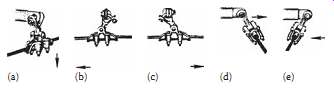
Above: FIG. 16 Suspension-type conductor holder. (a) through (e) shows the
flexibility of the holder, permitting movement of the conductor in all direction.
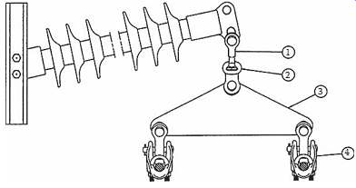
Above: FIG. 17 Suspension-type conductor holder for two bundle conductors.

Above: FIG. 18 Line termination on dead-end tower with two bundle conductors.
Insulators Bundle conductor interconnects the insulator ends. Spacer
Accessories
Most high-voltage transmission lines use aluminum cable steel-reinforced (ACSR) conductors or all aluminum conductors (AAC). These conductors are described in more details in section 22. The
conductor must be attached to the insulators at each tower. The attachment must prevent slipping, but must be flexible to minimize the mechanical stress on insulators and permit free movement of the conductors. FIG. 16 shows a suspension unit. The figure shows that this unit permits small conductor movement in all directions.
Extra-high-voltage lines use bundle conductors. Each phase contains two, three, or four conductors connected in parallel. The use of bundle conductors reduces the line-generated TV and radio interference, conductor impedance, and increases the maximum permitted phase current. As an example, the two bundle conductors require a suspension holder shown in FIG. 17.
Similar holders are available for three and four bundle conductors.
At the dead-end towers, the conductors are terminated at the insulators at both sides of the tower and a flexible conductor connects the two insulator ends together assuring the current flow, as shown in FIG. 18.
The hardware used for the line termination is shown in FIG. 19. This is a compression-type termination used for ACSR conductors up to 500 kV.
The conductor bundle requires spacers preventing the tangling of the conductors. FIG. 18 shows spacers on the interconnection at a dead-end tower. FIG. 20a shows dimensions of a spacer for two bundle conductors and the photograph in FIG. 20b shows a spacer used for three bundle conductors.
The wind generates Aeolian vibration on the transmission line conductors, which produces small amplitude (typically only a few centimeters) vertical movement of the conductor. Vortices on the leeward side of the conductor generate the vibration with a frequency between 5 and 150 Hz. The vibration produces periodic bending of the conductor, which causes fatigue failure of the conductor strands.
Most of the failure occurs at the towers where the conductor is clamped to the insulator.
The power companies install two vibration dampers at the end each span, close to the point where the conductor is clamped to the insulator. FIG. 21 shows a Stockbridge-type damper. A short (30-80 cm long) damper cable is attached to the conductor with a clamp. Two metal weights are connected at each end of the damper cable.
The vibration of the conductor will initiate swinging motion of the damper weights. The weights periodically hit the cable, which greatly damps the oscillation. The weights, the stiffness, and length of the damper cable are tuned to the vibration frequency.
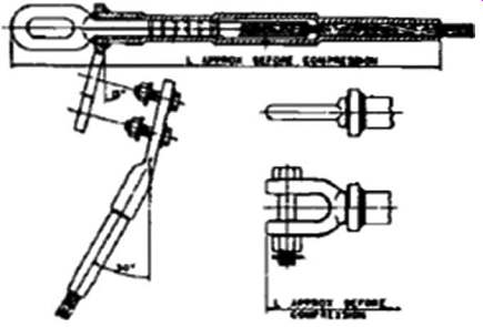
Above: FIG. 19 Compression dead end for ASCR conductors.
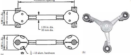
Above: FIG. 20 Conductor spacers. (a) Spacer for two conductors. (b) Spacer
for three conductors. (From AFL Telecommunication website: Conductor
accessories. )
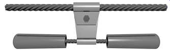
Above: FIG. 21 Stockbridge conductor vibration damper. (From AFL Telecommunication
website: Conductor
accessories.)