A shop needs two circuits, one for power tools and another for lighting.
Tapping Into Existing Circuits: If there already are two circuits in the shop, you may be able to add lighting and new outlets for portable power tools. If not, extending one or more circuits in adjoining locations may work (below and opposite).
Choose circuits not controlled by switches. To determine whether a circuit has enough spare capacity; add up the wattages of all the de vices that are likely to be drawing power from it at the same time. Divide the total by the number of volts carried by the circuit—either 120 or 240—to obtain the amps drawn, then subtract this amount from the amperage rating of the circuit. If the result is 10 or more amps, the circuit has enough spare capacity to run most tools.
Avoid tapping into existing circuits if your house wiring is aluminum or if you’ll be powering stationary tools. Additional circuits are called for.
New Circuits: Stationary power tools or an electric heater each require a dedicated circuit. Such circuits can originate from a 40-amp circuit breaker in the main panel, extend to an auxiliary panel called a subpanel with No. 8 cable, and branch off individually from the subpanel. Although you can install the subpanel and do the circuit wiring yourself, have an electrician connect the new circuit to the service panel.
Before you start wiring, check local electrical code requirements. For example, be sure to match each circuit’s wire size to the capacity of its circuit breaker or fuse. For 15- amp lighting circuits, use No. 14 copper wire; for 20-amp circuits, use No. 12 wire.
Reduce the chance of shock by installing ground-fault circuit interrupters (GFCIs), either in the form of a circuit breaker or a receptacle. Designed to detect minuscule cur rent leaks and cut off the circuit in 1/40th second, GFCI protection is required for 120-volt 15- and 20-amp circuits serving workbenches.
TOOLS:
- Voltage tester
- Cable ripper
- Wire stripper
- Punch
- Hammer
- Electric drill
- Masonry bit
- Maul
- Star drill
- Extension bits
- Putty knife
- Electrician’s fish tape
- Screwdriver
MATERIALS:
- Electrical cable
- Cable clamps
- Wire caps
- GFCI outlet
- Surface electrical box (3½”)
- Jumper wires
- Common nails (2¼”)
- 1 x 2s
- Cable staples
- Plastic pipe
- Latex concrete- patching com pound
- Cable straps
- Screw anchors and screws
- Light chain
- Electrician’s tape
- Sealing putty
- Plywood (3¼”)
- Circuit breakers
SAFETY TIPS: Wear goggles when operating power tools, nailing, or chiseling masonry.
EXTENDING EXISTING CIRCUITS
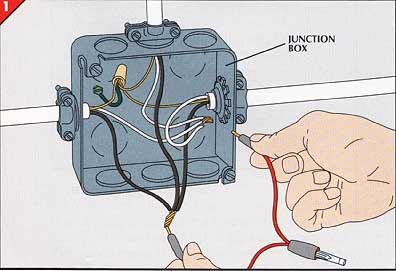
1. Locating a cable for tapping.
• Find a junction box on a circuit with extra capacity.
• Trip all the circuit breakers in the service panel and open the junction box. Remove wire caps and check all pairs of wires and grounds with a voltage tester, which will not glow if all the power is off.
• To identify the circuit at the service panel, have a helper turn on the circuit breakers one at a time until the voltage tester glows. Then have your helper operate any switches on the circuit. If the tester continues to glow, the circuit is suitable for tapping.
• Trip the circuit breaker for this circuit, then turn on all the other circuit breakers, restoring power to the rest of the house.
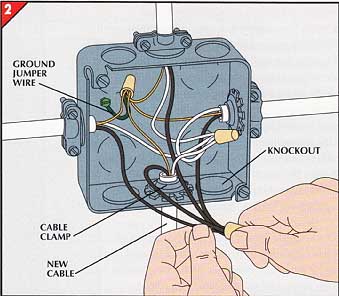
• Remove a knockout from the junction box with a punch and hammer and secure a cable clamp to the box.
• Strip 6 inches of sheathing from one end of a cable, strip inch of insulation from the end of each cable wire, then feed the cable through the cable clamp and tighten it.
• With wire caps, connect the cable’s bare copper wire to the other bare copper ground wires and the green ground jumper wire.
• Connect the cable’s white neutral wire to the white wires and its black wire to the black wires (right).
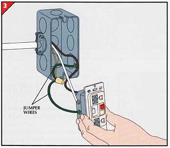
• To install a surface-style GFCI outlet at the workshop end of the new cable, fasten a 3 surface box to the wall. Remove a knockout hole on one side and secure a cable clamp. Strip the new cable, slide it into the box and fasten it with the cable clamp.
• Attach the white wire to the terminal screw marked LINE WHITE. Attach the black wire to the terminal screw marked LINE BLACK.
• Attach one green jumper wire to the terminal screw marked GROUND and another to the box. With wire caps, connect the cable’s bare copper wire to the green jumper wires.
• Screw the GFCI and an outlet cover to the box.
PATHWAYS FOR WIRES
To extend electrical cable to the shop from a location in another part of the house, use the framing members of an unfinished basement, crawl space, or attic as pathways. In a basement, you may be able to use a girder or the edge of a sill plate as a route (right). To run cable across joists, fasten 1 -by-2s perpendicular to the joists along the cable route to protect the cable from being snagged. Secure the cable with cable staples every 4 feet and within 1 foot of each cable end.
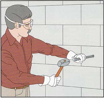
Passing through concrete block.
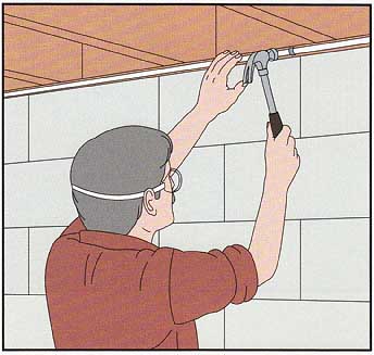
• With a masonry bit, drill a hole through the block for the cable. You are most likely to pierce through the hollow spaces in the block if you place the hole 3 inches from the end of the block and center it between the top and bottom.
• With a star drill and a maul (right), enlarge the hole to about 2 inches in diameter to accommodate a length of 1¼-inch-inside-diameter conduit, which will house the cable and cable clamp.
• Trim the conduit so it spans the opening and insert it into the hole. Plug the gap around the conduit with latex concrete-patching compound.
To run cable along a concrete-block wall, thread it through metal cable conduit secured to the block at 4-foot intervals with cable straps held by screws and plastic screw anchors.
CAUTION : Metal conduit must be grounded. Normally this requirement is met when it is secured to the subpanel or any grounded electrical box.
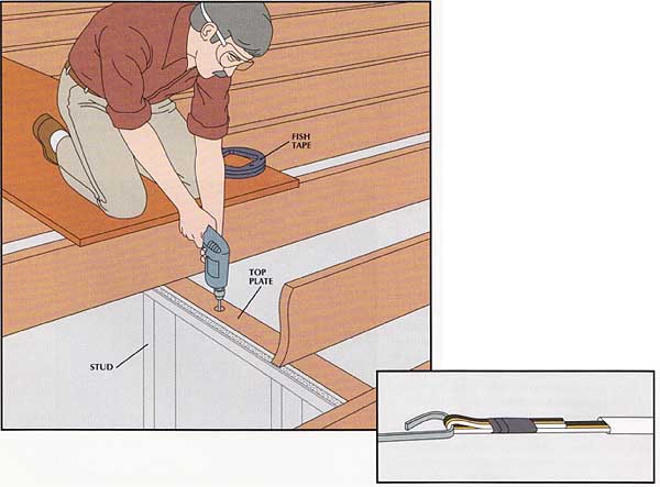
• In the attic, drill a hole through the top plate into the space between two studs. Then go to the basement and drill a hole up through the ground floor’s sole plate in line with the hole in the attic.
• Have a helper in the attic drop a light chain down through the hole in the top plate to the sole plate.
• From the basement, push a fish tape up through the sole plate hole, catch the chain, and pull it down through the hole. Secure the chain to the hook at the end of the fish tape with electrician’s tape.
• Have your helper pull the chain up until the fish tape reaches the attic. Remove the chain and attach the cable to the tape hook (inset).
• Pull the fish tape down until the end of the cable emerges from the sole plate.
ALL-PURPOSE WIRING LAYOUT
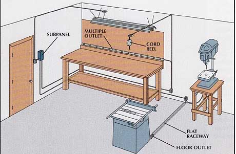
Laying out the cable and outlets.
In the shop illustrated at left, three separate circuits stem from a subpanel near the door. One feeds a switched circuit to a fluorescent light above the workbench. Another serves a string of outlets along the back of the bench for portable power tools; an overhead out let on a cord reel; and a standard wall outlet. A third circuit powers outlets located near stationary tools, including a floor outlet for the table saw. All cables are encased in steel conduit or raceway.
The circuit breakers for the bench out lets and the stationary tools can be shut off and the subpanel locked to prevent unauthorized use.
INSTALLING A SUBPANEL
• Run No. 8 three-conductor-with-ground cable from the service panel to the subpanel location. Leave 5 feet of extra cable at the service-panel end and 2 extra feet at the subpanel end.
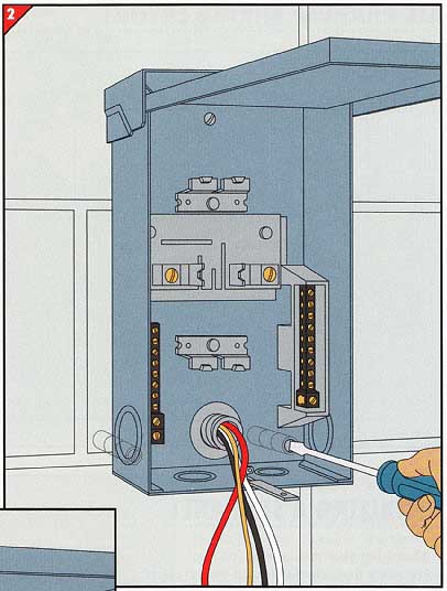
• For a cable entering the subpanel from the side, first mount the subpanel (Step 2), then clamp the cable and strip its sheathing.
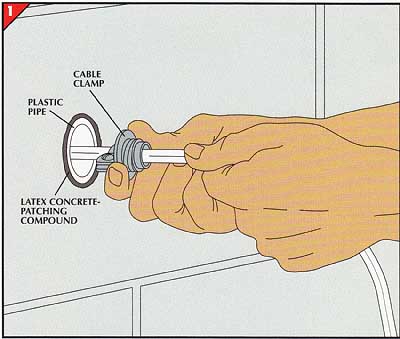
• If the cable will enter the back of the sub- panel, first thread a cable clamp over the cable, pack putty into the pipe around the cable, and slide the clamp to the wall, leaving a 2-foot end.
• Tighten the clamp’s screws to secure the cable, then push the gripping portion of the clamp into the pipe. Pack putty around the cable at the other end of the pipe.
• Strip the cable sheathing back to the clamp.
• If the cable is to enter from the rear, thread it temporarily through the hole in the box so the subpanel can fit flush against the wall. With a helper holding the subpanel against the wall, mark its mounting holes.
• Remove the subpanel from the wall and drill a hole at each mark. Insert lead or plastic screw anchors into the holes.
• Thread the cable through the subpanel box and, with the cable clamp against the back of the box, mount it by driving screws into the screw anchors.
If the wall is likely to be damp, as in basements, mount a piece of 3/4-inch plywood to the wall and secure the subpanel to it.
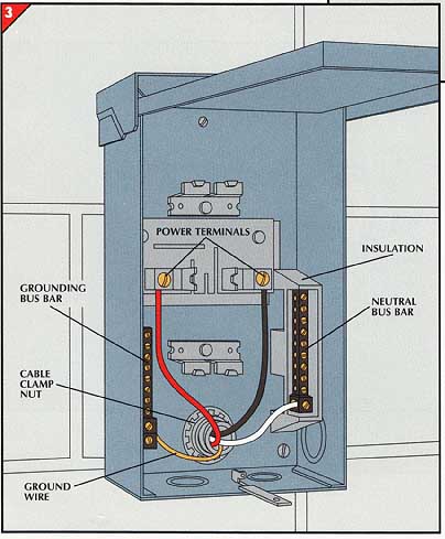
• Put the cable clamp nut on the clamp and tighten it against the box.
• Separate the four cable wires and strip ½-inch of insulation off their ends.
• Connect the four wires as follows: the bare ground wire to a large terminal on the uninsulated grounding bus bar, the white neutral wire to the large terminal on the insulated neutral bus bar, the black wire to one power terminal, and the red wire to the other power terminal.
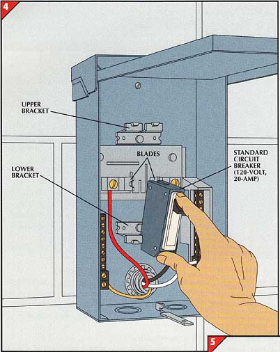
4. Installing a circuit breaker.
Snap a circuit breaker designed for your subpanel onto its holder in the box. To install a standard 120-volt, 20- amp breaker, suitable for a lighting circuit, in the model shown, first slip the breaker onto the lower bracket (left), then press it onto the blade connected to one 120-volt power terminal.
A 240-volt breaker would engage the two upper brackets and two blades, side by side; with each blade connected to a separate 120-volt terminal, the total capacity of the breaker would be 240 volts.
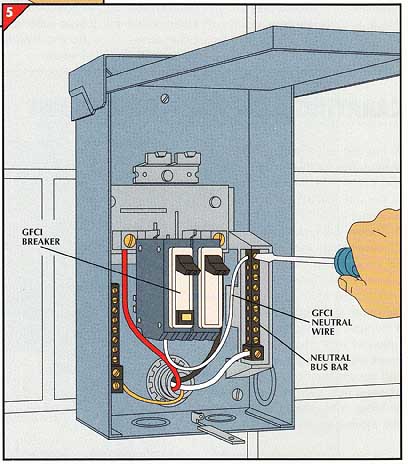
• Snap a 120- or 240-volt GFCI breaker into place as in Step 4.
• Uncoil the breaker’s white neutral wire and lead it to the insulated neutral bus bar of the subpanel.
• Cut the wire to fit and strip off inch of insulation.
• Fasten the wire to a free terminal on the neutral bus bar.
Next: Routing Power
through the Shop
Prev: Laying Out the Shop
