Once you have brought electrical power to the shop, you must then distribute it to outlets.
Wiring: New circuits from a sub- panel or the main service panel can be either 120 or 240 volts. Tools such as arc welders and certain stationary saws require a 240-volt circuit. Check electrical code requirements in your area, and when the electrician comes to hook up any new installations to the electrical service, have all your new wiring checked.
Outlets: A common duplex receptacle in a surface-mounted box can power a tool placed along a wall. Multi-outlet strips above a workbench are also convenient. Another option is to hang an extension-cord reel from the ceiling. If you buy a reconditioned stationary tool with out a built-in switch, you can install a lockable switch on it for safety and convenience.
Guarding Cables: Protect the wires to outlets with plastic or metal conduit or raceway. Thin-walled met al conduit (EMT) costs more than plastic tubes, which must be joined with cemented plastic fittings. The neatest but costliest option is rectangular metal raceway. Where the wiring needs to be flexible, armored cable offers security and is easy to install.
CAUTION: Metal conduit must be grounded. Normally this requirement is met when it is secured to the subpanel or any grounded electrical box.
TOOLS:
- Hacksaw Round file
- Carpenter’s level
- Screwdriver
- Cable ripper
- Ball-peen hammer
- Wire strippers
- Electric drill
- Punch
- Masonry bit
MATERIALS:
- Electrical conduit
- Conduit connectors
- Corner elbows
- Conduit straps
- Electric cable
- Cable clamps
- Screw anchors and screws
- Receptacles
- Jumper wires (green and black)
- Wire caps
- Outlet boxes
- Circuit breakers
- Multi-outlet strip
- Floor raceway kit
- Extension-cord reel
- Screw hook
- Switch box and safety plate
- Electrical cord
- Plug
- Armored cable, bushings, and clamps
- Junction box
SAFETY TIPS: Wear goggles when drilling into masonry.
CARRYING A CIRCUIT WITH CONDUIT
1. Laying out the conduit path.
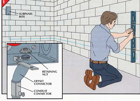
• Mark the locations of the outlets and junction boxes, then fasten them to the wall just as you secured the subpanel (Step 2).
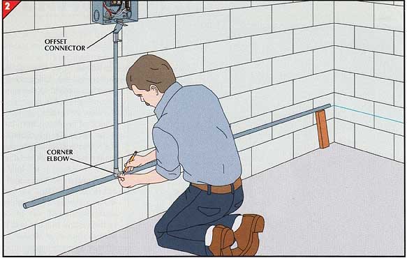
• Choose a knockout opening in the subpanel at an appropriate location for the circuit you are running. With a level, mark vertical and horizontal lines on the wall to trace the conduit path from the subpanel.
• Remove the knockout from the subpanel with a hammer and punch. Insert a conduit connector in the hole and secure the connector with its retaining nut. You may need to employ an offset connector to bring the conduit against the wall (inset).
• Mark a length of conduit to span between the subpanel and first run of horizontal conduit. Cut the conduit with a hacksaw and ream the inside rim with a round file to remove burrs, which can cut into cable.
• Secure one end to the connector at the sub-panel and add a corner elbow to the other end.
• Place the first horizontal piece in position, in this case leaving space for an elbow in the corner. Mark the piece where it crosses the vertical section, then cut it to length and attach it to the elbow.
• Continue to mark, cut, and add sections along the marked path to the next outlet location. Secure the conduit to the outlet box with a conduit connector. Install remaining conduit and boxes in the same manner.
3. Running cable.
• Disassemble all the fittings at their joints to facilitate running the cable through the conduit.
• Starting at the elbow nearest the middle of the run and working toward the ends, push two-conductor-with- ground cable through the conduit and fittings into the boxes at either end. Pull the cable taut , leaving about 8 inches of cable protruding from each box and at the subpanel, and cut it.
• Reassemble the conduit joints.
• To fasten the conduit to the wall, drill holes for screw anchors, then screw in straps, placing them 4 feet apart and within 1 foot of each end.
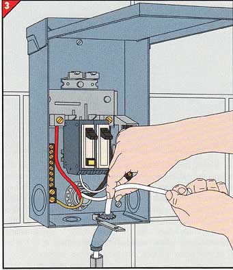
• Strip the cable sheathing back to the conduit connector.
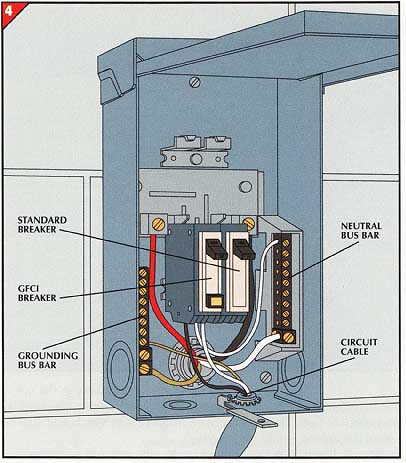
• Connect the bare ground wire of the circuit cable to the subpanel’s grounding bus bar.
• Prepare the other wires by stripping ½-inch of insulation from them.
• To wire a GFCI breaker, connect the white neutral wire to the terminal on the breaker marked with a white dot and labeled LOAD NEUTRAL. Connect the black wire to the terminal labeled LOAD.
• For a standard 120-volt breaker, attach the neutral wire of the cable to the neutral bus bar and the black wire to the circuit breaker terminal.
• Strip the cable wire ends.
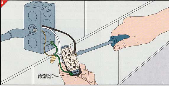
• Attach one green jumper wire to a screw terminal on the wall of the box and another to the green grounding terminal of the receptacle. With a wire cap, join both jumpers with the cable’s bare wire.
• Connect the white cable wire to a silver terminal of the receptacle and the black wire to a brass terminal.
• To extend the wiring to another outlet, install conduit in another knockout, then connect the cable’s bare wire to the green wires. Attach the cable’s white wire to the remaining silver terminal on the receptacle, and the black wire to the brass terminal.
WIRING A 240-VOLT CIRCUIT
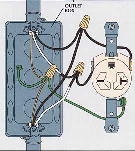
Connecting a 240-volt circuit breaker.
A 240-volt circuit can usually be wired with two-conductor- with-ground cable as shown here. High-wattage appliances such as kilns require a three-conductor-with-ground cable; its neutral conductor is attached to the neutral bus bar. Be fore wiring a circuit for a shop machine, check the owner’s manual for electrical requirements.
• Run conduit and cable to the subpanel box (Steps 1-3).
• Snap a 240-volt circuit breaker designed for the subpanel box into position (Step 4).
• Paint the end of the white wire black to indicate that it will be live, and not neutral.
• Wire the breaker by connecting the bare cable wire to the grounding bus bar, and the white and black wires to separate breaker terminals.
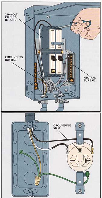
Adding a 240-volt outlet along a run.
• Attach short lengths of green jumper wire to the green grounding screws of the receptacle and the outlet box.
• Attach short black jumper wires to each of the remaining terminals on the receptacle. (The receptacle can be oriented with the grounding slot up or down.)
• Paint the ends of the white wires black to indicate that they will be live.
• With a wire cap, join the bare wires from the two cables and the two green jumper wires. Connect the two black cable wires to one of the black jumper wires on the receptacle, and the white cable wires to the other black jumper wire.
• Screw the receptacle in place and attach a cover.
A 240-volt outlet at the end of a run.
• Fasten short green jumper wires to the green grounding screws of the receptacle and outlet box.
• With a wire cap, connect the cable’s bare ground wire to the green jumper wires.
• Paint the end of the white wire black to indicate that it will be live.
• Fasten the black cable wire to the brass terminal screw on the receptacle, and the white wire to the silver screw.
OUTLETS THAT BRING POWER TO THE JOB
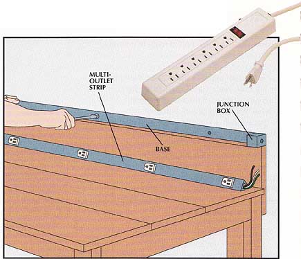
Mounting a multi-outlet strip.
• Screw the base of a multi-outlet strip to the wall so the small junction box is at the end where power will enter (right), and run conduit and cable to it. For portable power tools, consider mounting the strip on the front of the bench to keep the cords out of the way.
• With wire caps, connect the bare cable wire to the green wire of the outlet strip; the white cable wire to the white outlet wire; and the black cable wire to the black outlet wire.
• At the other end of the strip, connect the green wire to the grounding clip that clamps into the outlet-strip base. Cover exposed wire ends with wire caps.
• Snap the outlet strip onto the base.
A power bar with an internal circuit breaker (photo) is a simpler version of a multi-outlet strip.
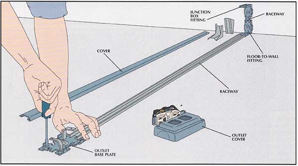
• Place the base plate of a raceway floor outlet box in the desired location, then lay out pre-scored raceway and fittings on the floor.
• Snap off the raceway to the correct length, or cut it with a hack saw. Cut each cover section inch shorter than the corresponding length of raceway.
• Drill holes in the floor for screw anchors, then fasten the raceway and base plate to the floor.
• Lay cable inside the raceway and connect it to the receptacle (Step 5).
• Fasten the receptacle to the base plate and snap the cover sections over the raceway. Attach the outlet cover, twisting out the scored semi circle to fit it over the raceway.
• To complete the circuit, run cable in conduit from the subpanel to the junction-box fitting. Add a junction box, then connect the two cables. Finally, cover the floor-to-wall and junction-box fittings.
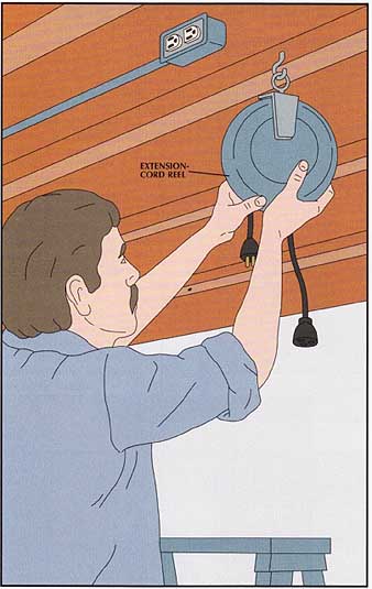
Hanging an extension reel.
An extension-cord reel can neatly store heavy-duty cords 50 feet or longer.
• Drive a screw hook into a joist at a convenient point and hang a cord reel from it.
• Install an outlet box on the joist within reach of the cord-reel plug and run conduit and cable from the box to a source of power.
• Connect the cable to the outlet and mount it in the box.
• Put the cover on the outlet box and plug in the cord reel.
== A Power-Cord Cover ==
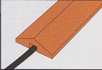
Power cords lying across the floor are both an electrical and a tripping
hazard. While raceway is most suitable for a permanent installation, other
solutions are available, For example, you can temporarily secure a cord
to the floor with duct tape. A more permanent alter native is to buy a rubber
cord protector—or you can make wooden one in your shop from a 1 -by-3.
Cut the board to length, then use a router to groove one face of the board for the cord. Bevel the other face so that the cord protector presents less of an obstacle.
==
INSTALLING A SWITCH FOR A STATIONARY POWER TOOL
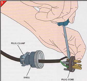
1. Attaching the plug.
• Mount a switch box in a convenient location on the tool stand.
• Cut a length of Type Si three-wire flexible cord, sized in accordance with the tool’s cur rent rating, to reach from the outlet to the switch box.
• Loosen the screws on the face of the plug to separate the plug core and shell.
• Slip the shell over the cord, then remove 1½-inches of sheathing to expose the three wires.
• Strip inch of insulation from each wire end and connect the wires to the plug terminal screws — black wire to the brass screw, white wire to the silver screw, and green wire to the green screw.
• Reassemble the plug and secure it with the faceplate screws. Tighten the plug clamp.
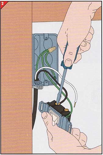
2. Wiring a switch to the cord.
• With a hammer and punch, remove a knockout from a switch box.
• Secure a cable clamp to the box, strip 6 inches of sheathing from the end of the cord, and thread it through the knockout hole in the box; tighten the clamp around it.
• Attach short lengths of green jumper wire to the green grounding screws of the switch and outlet box.
• With a wire cap, join the cord’s green wire and the two green jumper wires. Attach the black wire to one of the terminal screws on the side of the switch; do not attach the white wire yet.
• With a hacksaw, cut a length of armored cable to fit between the switch box and the tool’s junction box.
• Remove 4 inches of the armor from the cable at each end. To do so: Cut perpendicular to the direction of the spirals, then break off the armor.
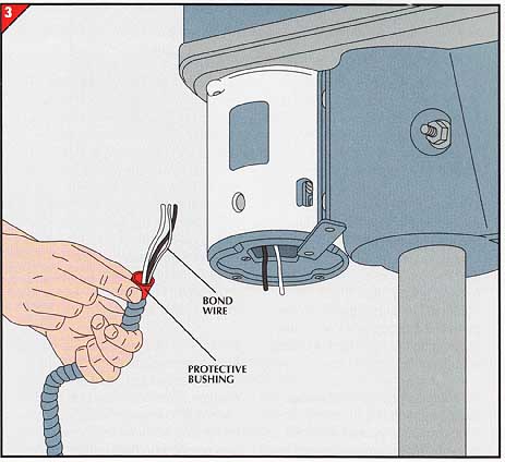
• Insert a protective bushing into each end of the cable armor; wrap the thin bond wire back around the cable armor to secure the bushing.
• Fasten the cable to the motor with cable clamps designed for armored cable.
• Connect the wires at the motor as indicated on the manufacturer’s specification plate or on the diagram in the junction box.
• At the switch box, fasten the cable with cable clamps designed for armored cable. Connect the white cable wire to the white wire of the flexible cord, and the black cable wire to the remaining screw terminal of the switch.
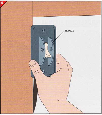
On the box, mount a switch cover-plate equipped with safety flanges drilled for a pad lock. The flanges help prevent clothing from accidentally trip ping the switch. A lock through the holes guards against unauthorized use of the tool.
Next: Lighting Up
a Shop
Prev: Bringing Electricity
to the Shop
