AMAZON multi-meters discounts AMAZON oscilloscope discounts
Fire on board an aircraft is a very serious hazard; all precautions must be taken to minimize the risk of a fire starting. In the event that a fire does occur, there must be adequate fire protection on the aircraft. Fire protection includes the means of both detecting and extinguishing the fire. The subject of fire protection theory is a branch of engineering in its own right. Basic fire protection theory is covered in this section to provide the reader with sufficient information to understand how this theory is applied through aircraft electrical systems. The section focuses on the equipment and systems used to detect fire and smoke together with the means of delivering the fire-extinguishing agent.
1. Overview
The type of fire protection systems and equipment
fitted to an aircraft can be sub-divided into specific areas of the aircraft:
-- engines/APU
-- cargo bay
-- passenger cabin
The fire protection technologies used on aircraft depend on these areas and specified fire risk. In addition to the fire risk in these areas, high temperatures resulting from engine bleed air leaks can also be hazardous. Bleed air is tapped from the compressor stage of a gas turbine engine, distributed in the pneumatic system for a number of purposes including thermal anti-icing. The consequences of hot air leaks are less severe than fire, but overheats can weaken structure and damage components. The pneumatic system takes air from the engines and distributes it through out the aircraft; typical areas that are fitted with dedicated overheat detection systems are the wing leading edges, in the wheel wells and under the cabin floor.
Up until the 1990s, the two agents used extensively in the aircraft industry were:
-- bromochlorodifluoromethane, also known by the trade name Halon 1211, or BCF
-- bromotrifluoromethane, also known by the trade name Halon 1301, or BTM.
These are both inert gases and are either applied locally (typically in hand-held extinguishers) or as total flooding applications (typically in cargo bays). Both these agents are very effective at extinguishing fires, however they are in a group of halogenated hydrocarbons that have been shown to contribute to depletion of the earth's ozone layer. Although halon fire extinguishers are still being specified on air craft, both gases come under the terms of the 1989 Montreal Protocol (and subsequent revisions), that prohibits the new production of these agents. The industry is supporting the supply of halon 1211 and 1301 through recycling of existing halon stocks for in-service and new production aircraft.
Alternative and replacement agents are being developed, and these are gradually being introduced throughout the fire protection industry. Examples of agents that do not deplete the ozone layer include:
-- water
-- dry powder
-- vaporizing liquids (gaseous agents)
Combustion can be defined as a rapid and complex chemical reaction in which light and heat are evolved.
All equipment in an aircraft is carefully designed and tested so that there is a low probability of starting and sustaining fire. Three factors are required to initiate and sustain combustion:
-- fuel
-- heat
-- oxygen
========
Table 1 Fire classifications and extinguishing strategies
Class of fire Fuel/heat source Appropriate extinguishing strategies
Class A Solid/organic Water, vaporizing gas
Class B Flammable liquids Carbon dioxide, dry powder, or vaporizing liquid
Class C Flammable gasses Dry powder, vaporizing liquids
Class D Metals Dry powder
Class E Electrical equipment Carbon dioxide, dry powder, or vaporizing liquid
Class F Cooking fat/oil Carbon dioxide, dry powder, or vaporizing liquid
=========
Fuels include solids, liquids and gases; each type of fuel requires a minimum temperature to be reached and maintained. Oxygen is normally available from the ambient air. The type of fire detector and extinguishing agent deployed is largely determined by which fuel is likely to combust. Detecting a fire can be achieved by one or more of the following strategies:
-- thermal sensors
-- optical sensors
-- smoke detectors
Extinguishing a fire can be achieved by one or more of the following strategies:
-- limiting or eliminating the fuel
-- limiting or eliminating the oxygen
--reducing the temperature of the fire
-- interfering with the chemical reaction
Fires can be categorized by the types of fuel that are combusting; this in turn determines the detection and extinguishing strategy. There are several classifications of fire used in the USA, Europe and Australasia.
Typical fire classifications and extinguishing strategies are illustrated in Table 1.
Primarily sources of risk/fuel in aircraft applications are:
-- engines and APUs: class B
-- cabin/flight compartment: class A
-- cargo bay: class A.
Key point
Electrical fires are sometimes stated as Class E, or combined as Class A, B and D. The strategy adopted for this type of fire is to isolate electrical power and then deploy the agent.
Each of the fire extinguishing agents has different attributes. Water reduces the heat in a fire. It is often mixed with an additive, glycol, to enable it to be used in sub-zero temperatures. Vaporizing liquids reduce heat, but their significant contribution is to interfere with the chemical reaction of the fire. Carbon dioxide (CO2 ) and dry powder both reduce the fuel's tempera ture and reduces the oxygen levels.
Key maintenance point
Always consult with the appropriate authority before deploying fire extinguishers.
2. Engine/APU fire detection
Engine/APU fire detectors are designed to very standards; they are needed when other systems, procedures and safety features have failed to prevent a hazardous situation developing.
In terms of fire protection, the engines and auxiliary power unit (APU) can be considered as having the same requirements. Fire detection within an air craft engine can be achieved by thermal and/or optical methods. Thermal fire detectors sense heat energy that is radiated from the fire; they can be either unit detectors (sometimes referred to as point, or ' spot ' detectors) or linear detectors. Optical fire detectors are based on sensing ultraviolet (UV) or infrared (IR) energy.
Whatever the sensor technology, the engine is fitted with sensors in positions that provide coverage of all areas where a fire could start; these positions are determined mainly from experience with an engine type. Ignition sources within the engine are electrical faults, and hot surfaces, e.g. exhaust ducts. Fuel and/ or oil supply line failures in the engine will provide the means of sustaining the fire. There is a ready sup ply of oxygen in the ventilation air that is used to cool components.
When a fire is detected, the warning system activates an alarm bell and illuminates red warning lights in the flight compartment. The fire warning also illuminates a master warning light and another light (typically in the fire handle) to identify the affected engine(s). When the crew confirm that they have an engine fire, they operate the fire handle by first pulling and then twisting the handle. The action of pulling the fire handle activates micro-switches that shuts down the engine by:
-- closing the fuel shutoff valves
-- opening the field circuit of that engine's generator(s)
-- closing the bleed air supply from the engine into the pneumatic system
-- closing the hydraulic systems engine driven pump shutoff valve
If the fire warning continues for a prescribed time after these actions, the fire handle is twisted; this closes micro-switches that activate the engine fire extinguisher.
2.1 Thermal fire detection
There are various techniques used to detect fire and overheat by including unit (or spot detectors), linear detectors and optical sensors.
2.1.1 Unit fire detectors
These are effectively thermostatic overheat switches based on the bimetallic principle. FIG. 1 illustrates the external features and internal view and electrical schematic of a typical overheat switch. The two contacts are attached to spring bows; these are compressed during assembly and held apart by the outer barrel of the switch. As the detector is heated, it expands and the two contacts close, thus completing the warning circuit. An adjusting screw is found on the end-cap of some switches to allow for minor adjustments of operating temperature.
This type of detector can be used in engine fire detection systems; alternatively it can be used in the bleed air overheat detection system. The detector can only sense fire/overheat in a localized volume of the installation; it is more likely that multiple detectors are used to provide increased detection probability.
A small gas turbine engine would typically be fitted with six of these detectors.
The wing leading of a large aircraft could be fitted with over 20 overheat switches. The switches are connected in parallel as shown in FIG. 2; this forms a detection loop. If any one of the switches closes due to a fire or overheat being detected, the alarm circuit is activated thereby illuminating a system warning light. A simple test circuit allows some of the circuit to be tested from the flight compartment. Some air craft are fitted with a dual loop of detectors to provide a back-up system in the event of loop failure, e.g. open circuit wiring.
==========
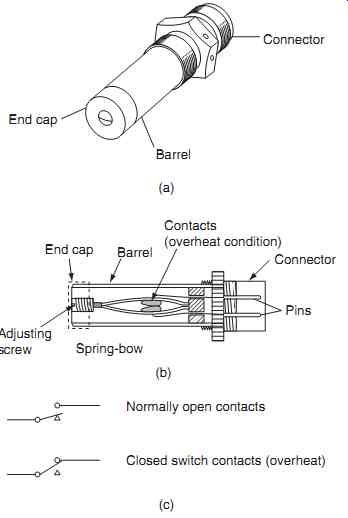
FIG. 1 Overheat switch: (a) external features, (b) internal features, (c)
electrical schematic
===========
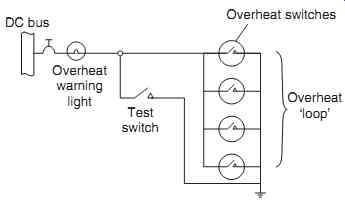
FIG. 2 Overheat switches connected in parallel
=============
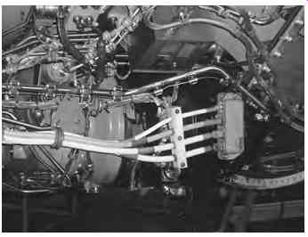
FIG. 3 Linear sensor installation
==========
Test your understanding
How would the crew know if more than one switch in a multiple detection system went into alarm?
Key maintenance point
The individual thermostat switch cannot be easily tested on the aircraft.
The actual alarm temperature of the unit fire detector is set by the amount of compression on the bow springs. During the aircraft design phase, the normal ambient temperature of the zone being protected is determined. The alarm temperature setting of the fire detector has to be carefully selected by the system designers. If it is too close to the nominal ambient temperature, there is a risk of false warnings. An operating temperature far higher than the zone's nominal ambient temperature will cause delays in the switch operating (if at all). Aircraft specifications and designs vary; however, a margin of approximately 50°C between ambient and operate temperature is typical. Detectors with different alarm temperatures are sometimes fitted in the same loop; this takes into account varying ambient temperatures in different zones. Typical settings are 230°C in the cooler forward sections of the engine nacelle and 370°C in the aft sections of the nacelle.
2.1.2 Linear fire detectors
Greater coverage of the engine nacelle can be achieved with linear fire detectors. Three types of linear fire detectors are used on aircraft; these are based on averaging or discrete detectors. The alarm temperature of averaging linear detectors depends on the length of element heated. Discrete linear detector systems are essentially independent of the length of element heated to provide an alarm; these eutectic salt. The response time for any fire detector is critical to the safety of the aircraft; the standard test for a linear fire detector is for it to respond to a 1100°C flame with five seconds. Actual response time will depend on many factors including the convection of heat energy; this is why it is so important to route the fire detector in the critical areas of the engine nacelle.
Linear fire detectors are manufactured in lengths of up to three meters; some types can be joined in series to so that all these areas can be covered in convenient lengths. Installing the detector in manageable lengths facilitates installation and removal during maintenance.
Averaging linear detectors are based on either thermistor or pneumatic principles. Both detectors consist of a thin (typically 2 mm diameter) sensor that is routed around the engine. The sensor is attached to the engine using clips and bushes, see FIG. 3. The thermistor type fire detector is constructed in a coaxial form with a corrosion-resistant (typically stainless steel) outer sheath, nickel-chrome center wire and temperature-sensitive separating, or insulating material, typically very fine granules of a silicon compound. FIG. 4 illustrates the detector's physical features, a detector loop and the resistance temperature characteristics. This forms a complete electrical circuit, or fire detector loop.
===========
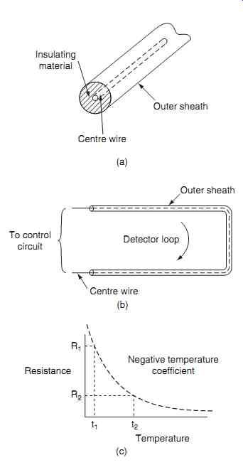
FIG. 4 Linear fire detector principles: (a) external features (b) detector
loop, (c) resistance/temperature characteristics
============
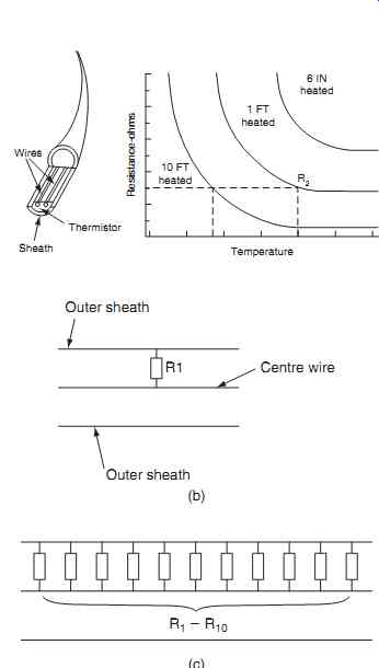
FIG. 5 Thermistor characteristics: (a) effect of length being heated, (b)
short length heated, (c) longer length heated.
=============
Referring to FIG. 4(c), when the sensor is at low ambient temperature (t1), the resistance (R1) between the outer sheath and center wire is very high. The silicon insulating material has a negative temperature coefficient, i.e. when the sensor is heated, the resistance of the insulating material decreases.
When this temperature reaches the alarm point (t2), the control unit senses a predetermined value, typically 1 k-Ohm. A relay contact in the control unit closes and this activates the alarm circuit. When the fire has been extinguished, the sensor cools down, causing the resistance to increase; the relay opens and the alarm circuit is deactivated.
The thermistor fire detector is an averaging type, responsive to the length of element heated, see FIG. 5. It can be seen that if the alarm is tripped at an equivalent resistance indicated by R2, a shorter length operates at a higher temperature. The thermistor fire detector can be thought of as an infinite number of resistors connecting the center wire to the outer sheath.
If only one of these imaginary resistors is heated, i.e. a short length of element, R1 has to reach a high temperature before its resistance drops to the alarm point. If a large number of these imaginary resistors is heated, i.e. a longer length of element, since the resistors R1 through R10 are in parallel, the alarm point will be reached at a lower temperature.
There are certain fault conditions that can lead to false fire warnings; these can be caused by moisture ingress into the sensor and/or short circuit of the sensor wiring. Control units have been developed with the ability to discriminate between fire and fault conditions. Moisture ingress into the connectors is pre vented by hermitically sealed terminal lugs.
Testing of the system is via a test switch located in the flight compartment. When the test circuit is activated, the following aspects are checked:
-- continuity of center element
--resistance of the insulating material
-- alarm circuit.
Key maintenance point: It is very important that the sensing element and wiring does not come into contact with the engine structure.
========
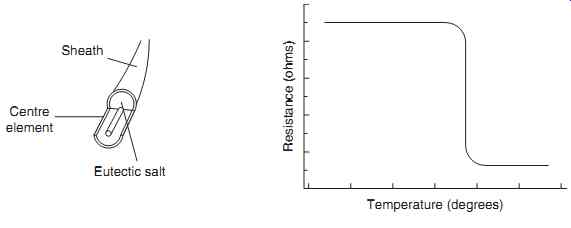
FIG. 6 Eutectic salt overheat
Center element; Eutectic salt; Sheath; Temperature (degrees); Resistance (ohms)
=========
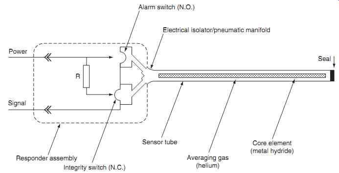
FIG. 7 Pneumatic detector schematic
==========
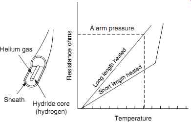
FIG. 8 Pneumatic detector characteristics
Temperature; Helium gas; Sheath; Hydride core (hydrogen); Resistance ohms; Alarm pressure; Long length heated; Short length heated
==============
Test your understanding: Why are averaging fire detectors dependent on the length of element heated to trigger an alarm?
Key maintenance point: Abrasion of the outer sheath will expose the insulating material leading to moisture ingress, decreased resistance and potential false warnings.
Key maintenance point: A short circuit on the sensor wires could be interpreted by the control unit as a fire condition.
Eutectic salt overheat detectors are constructed from a thin (typically 2 mm diameter) tube filled with a salt compound. They are particularly effective at detecting overheats when only a short length of element is heated. Referring to FIG. 6, the insulating material in this type of detector is a salt compound that melts at a specific temperature. All of the constituents crystallize simultaneously at this temperature and the insulation changes state into a molten liquid solution.
As with the thermistor system, a control unit monitors the resistance between the inner conductor and the outer sheath. When the salt melts, the resistance drops very rapidly and the control unit signals a warning. The resistance between the outer sheath and inner conductor decreases and the control unit senses this as a fire and/or overheat condition.
When the temperature is reduced, the salt compound solidifies and the resistance increases, thereby resetting the alarm output. This type of detector is used in both engine fire detection and bleed air overheat detection applications. The discrete detector is ideally suited for the detection of hot air leaks in:
-- wing leading edges
-- wheel wells
-- under floor locations
Pneumatic fire detectors are constructed from a thin (typically 2 mm diameter) sensor tube filled with helium, and a gas-charged metal-hydride center core. The tube is sealed at one end and attached to a pressure-sensing device (the responder) at the other end. The responder assembly is electrically isolated from the sensing tube and contains two pres sure switches, a resistor and electrical connector, see FIG. 7.
The normally open (NO) alarm switch is closed when a fire or overheat causes the helium to expand.
A normally closed (NC) integrity switch in the responder is held closed by the helium pressure; the internal resistor and switch contacts form the warning circuit. Measurement of the resistor value by an external circuit provides an indication of fire, over heat or loss of integrity. In the non-alarm condition, a monitoring circuit detects the known resistor value.
When large sections of the sensor tube are heated, the increased pressure of the helium causes the alarm switch to close; this bypasses the resistor and the monitoring circuit signals an alarm condition. When the overheat condition is removed, the gas pressure decreases and the switch opens.
If only a small section of sensor tube is heated, there will be insufficient helium gas pressure to operate the alarm switch. To accommodate this localized heating, the center core is formed with a metallic hydride compound which liberates hydrogen when rapidly heated; this now provides sufficient gas pres sure to operate the alarm switch. When the sensor cools, the hydrogen is re-absorbed back into the center core, pressure reduces and the alarm switch opens.
Should a leak develop in the sensor or responder, the integrity switch opens. The control unit detects an open circuit condition from the change of resistance and this is signaled as a fault condition. The characteristics of a pneumatic detector are shown in FIG. 8. The entire assembly is hermitically sealed; the responder can be located in the engine fire zone as illustrated in FIG. 9.
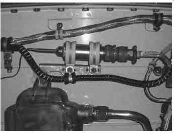
FIG. 9 Responder located in the engine fire zone
Key point: Thermal fire and overheat detectors are often installed as dual loops to ensure that fire detection is available even if one system is inoperative.
Key point: Dual loop fire detector systems can also be configured to only go into alarm if both loops sense fire, thereby reducing the possibility of a false warning.
2.2 Optical fire detection
Optical sensors sense the light emitted from a flame in much the same way that a person recognizes fires.
Our brains can distinguish between the light energy from a fire and the light energy from another source, e.g. a light bulb. The optical fire detector (or sensor) also has to be able to make this distinction. Some aircraft use optical fire detectors in place of thermal detector elements to simplify the installation.
Depending on the size of engine, several optical sensors may be required. The sensors are easier to install and maintain than linear detector elements. Optical sensors offer the advantage of being able to monitor a specific volume of engine nacelle.
The spectral analysis of a hydrocarbon fuel fire reveals peaks of energy in the infrared (IR) and ultraviolet (UV) frequencies bands. Optical fire detectors are designed to detect radiation one or both of these frequency bands. The type of detection technology used depends on a number of factors including the:
-- speed of response to a fire
-- ambient temperature for where the sensor is located
-- likely source of potential false alarms
One of the characteristics of burning fuel in an aircraft engine is the emission of infrared (IR) radiation. A particular feature of a hydrocarbon fire is that it emits a high energy level at a nominal 4.4 micron band of the infrared radiation, referred to as the CO2 spike, see FIG. 10(a). This is caused by the emission of energy from excited CO2 molecules burning in the fuel.
Detecting a fire is one thing; being able to discriminate against other light sources is a vital part of the optical detector's performance. Extraneous light sources that are capable of causing a nuisance alarm emit very low levels of radiation in this range. These sources include:
-- lightning
-- arc welding
-- x-rays
-- sunlight
-- hot surfaces
An IR sensor designed for this specific frequency band provides a high level of reliable fire detection, while being relatively immune to nuisance alarm signals.
The detection cell incorporates a pyro-electric cell and an optical filter; the latter only transmits radiation within the wavelength band of 4.2 to 4.7 microns.
This is packaged in a one-inch-diameter, three inches-long cylindrical housing with an optical window at one end and electrical connector at the other.
The pyro-electric detection cell responds to a fire by generating a signal when 4.4 micron radiation energy is detected. The optical fire detector has a cone of vision as illustrated in FIG. 10(b); 100% represents the maximum detection distance for a given fire. The sensitivity of the detector increases as the angle of incidence decreases.
As with any fire detector (whether thermal or optical) The response time of the detector depends on the:
-- size of the fire
-- rate of propagation
-- type of fuel burning
-- distance from the detector.
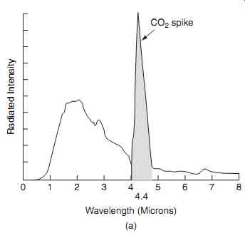
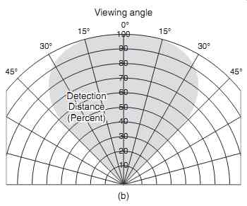
FIG. 10 Optical fire detection: (a) hydrocarbon fire and 4.4 micron CO2 '
spike ', (b) optical fire detector viewing angle
The average response time of aircraft engine fire detectors is less than five seconds; this is in response to a standard 1100°C, six-inch-diameter flame.
A typical turbine engine fitted to a medium-sized general aviation (GA) aircraft is installed with three IR optical detectors in each engine nacelle, a control amplifier, warning lights and test switch. The detectors are positioned to receive direct and indirect radiation from flames, thus providing optimum coverage of the nacelle.
Key point
Increased temperature as a result of a fire is not a factor in the operation of an optical sensor.
Key point
The IR cell's output is an electrical signal proportional to the amount of IR energy falling onto it.